Replacing transformers

Status
Not open for further replies.

docs

Member (SA)
So I have a blown transformer with the following details according to the service manual:

120/220 AC
50/60 Hz
13.5v DC

The power consumption of the unit is 19W.

The need to replace with very close or like for like raises questions in knowing that when buying a new replacement, how can you be certain it is a good replacement?

The 120/220 could be changed to a standard 240 without the need to use the switch for different countries.
Also, the DC output is 13.5v so needs to match.
But I don't often see options on adverts in ebay for wattage requirements.

In this scenario what would you go for as a very good match and how do you know if the transformer is a single or dual output?
 

Radio raheem

Requiem Æternam
Only ever replaced them with originals so not much help there, good luck

ie replaced 100v with 240v uk spec ones but all were original in the first place
 
Last edited:

docs

Member (SA)
It is an unusual one in that it takes 9 batteries, hence the 13.5v.
But DC input is 12v.
The unit is a pioneer sk-71.
 

Radio raheem

Requiem Æternam
All i can suggest is to replace the blown parts on the transformer or see if you have anything similar on you're parts boxes

my friend, i think i had one of those donkeys years ago
 

Superduper

Moderator
Staff member
Actually the specs you quoted is not for the transformer, it is the boombox ratings. If you get a 240v transformer that is 13.5v and has the same physical size, it will almost certainly be OK. The watt capacity usually corresponds to the physical size of the transformer. The watts aren't critical because ratings are often all over the place and 19w is quite low, I suspect a 28-30w version would be fine. In fact, a 12V transformer will probably output close to 15v DC after rectification. I wouldn't get anything rated lower than 19w though. To retain 120/240v capacity, just get a transformer with dual primary windings. You would connect those 2 windings either in parallel or in series depending on the input voltage. Generally speaking, the physical size of the transformer is the limiting factor so that is the first thing to try to match.
 
  • Like
Reactions: Hajidub

docs

Member (SA)
Thanks Norm, agreed, the physical size is quite small and only matched size wise to an ebay China transformer but the specs don't really match.
eBay link
OR
eBay link

The measurements I need match the ei48*26 in this list but as I said, the other specs do not match.
Screw holes (F) are 61 while E is 72.

Is there a good source online I could order from?

transformer specifications.jpeg
 

Superduper

Moderator
Staff member
Try F5-12 or FD5-12(dual primaries) from:
https://www.triadmagnetics.com

Their stuff are sold by most major electronics suppliers including Mouser.com and Digikey.com. I'm pretty sure Farnell has or can get them too. Forget the VA, it is what it is for that physical size. Essentially, the size of the winding pack dictates the VA capacity. In other words, you can only eek out so much current from a certain size windings. Ideally, if you can fit in a FD6-12, it would be much better and that would be the size you'd find in an M9994. However, I do recall Pioneers are very low powered boomboxes. Probably something like 2wpc or something. The specs on the service manual might not be a continuous rating (which transformers are rated at) but rather a burst momentary figure. Or maybe that's why the Xformer burnt out. Typically, transformers are nothing but a wire winding so if used within it's rated capacity, should never burn out. Again, see if you can shoehorn an FD6-12.
 

docs

Member (SA)
I think it burnt out because as usual someone powered it up with 240v while it was set to 120v. Sadly there isn't anything to save the transformer that I can see in the sm.
 

hopey

Member (SA)
it maybe along shot but It looks like the TX in radios are bespoke, so maybe find another donor box. Even newish ones have the small TX inside.
 

docs

Member (SA)
Norm, it might be quite hard for me to purchase one of those from the US, perhaps this is something you can help with? Or I need to find somewhere in the UK to buy one.
 

Superduper

Moderator
Staff member
Dave, just get one from here:
If that link doesn't work, just go to mouser.co.uk and search for FD5-12

I can buy and ship to you, but it makes absolutely zero sense. USA shipping service pays the highest shipping charges in the world. It's because international rates are set based on economy rankings, and USA is #1 in the world, so we pay by far the most. We can buy something and get it shipped from China to our door, but it costs us less than just the shipping charge to mail the same thing the next city over, even if it was free, we could not compete with China. I checked and the shipping charges to UK would be like $27 for first class and around $43 for priority mail which includes shipping and tracking. The transformer costs only £10.26 therefore it always makes more sense to get it from your own country.
 

docs

Member (SA)
Little help in connecting this please.
Existing transformer has 3 inputs, white, yellow, purple and 2 outputs both red.

1648064151349.png

The new transformer has 4 inputs and 3 outputs.

According to the new transformer schematic, does this look right?
And does it matter which output red goes to which on the output board?
Thanks

1648064439403.png
 

hopey

Member (SA)
The Primary looks like it has two separate windings not centre tap. You should check the resistance to find your 240v winding. Output is AC so shouldn't matter it rectifies on the PCB.
 

Superduper

Moderator
Staff member
Your proposed hookup is correct for a dual winding 120/240 transformer. This is the correct and best way to make up that arrangement (more on that later).

The factory used a single winding center tap configuration. Technically, it is correct that running 120v through a tap to one of the end winding terminals will allow it to output the same secondary voltage, as if 220v was run from end to end. However, when using the center tap with 120V input to get the same output voltage, you'll also end up with only 60% of the VA output as in the 220v configuration.

On the schematic, you'll notice that the primary tap is not in the middle. It is offset since 120V is not 1/2 of 220. This is also the reason the transformer probably blew up. I presume you are operating it in a 240V environment? People constantly say oh yeah, I use a 100V boombox in a 120V region and it's OK. Ok, but if you crank it up, maybe it's still OK. Maybe not. If it was still under warranty, it's almost a guarantee it won't be warrantied if used with 240V.

Unfortunately, the input voltage switching circuit is simple and not compatible with a dual winding setup. You can modify it but if the boombox is never going to a 120V region, just ignore it.

About the secondary center tap-- you can safely ignore or snip it. You won't need it. It would make it very convenient if you are setting up a dual supply circuit (such as one that has +DC/-DC type system), but for this and most boomboxes, you won't need it.

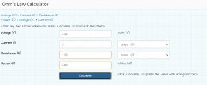
If you wanna play with ohms law, you'll be able to figure this out on your own. Suffice it to say that if you run 240V through 2 identical transformer coils run in series, you'll get a certain VA. If you run 1/2 the voltage though 2 separate coils, run in parallel, you'll consume twice the current but the final VA will be the same. This will not be the case with a middle tapped transformer since you cannot split the coils to run them in parallel. Therefore you'll only get a fraction of the output. If it was a center tap, you'll get 1/2 the output since only 1/2 of the primary coils will be used.

------------------------------------

If you are getting confused, just connect them in series, make sure the phase connections are correct, or else the fields will cancel themselves out & you'll end up with no output, maybe damage the transformer. Before connecting the secondaries to the boombox, meter them (on AC) to ensure you are getting the proper output voltage. If it's wrong (0, or 1/2 or 2x the expected amount), stop and recheck. At least by replacing the transformer with a correct 240v unit (instead of 220v version), you are correcting the power supply to enable proper 240v operation. If it reads slightly low, don't worry. The voltage will jump up significantly once rectified to DC.
 
Last edited:

docs

Member (SA)
Thanks Norm and hopey, i've wired it up as per my diagram but as you suggested I left the 2 red wires disconnected to check their voltage. Roughly 1.5v on the red wires on 220v setting, seems low.

Wired up as per diagram and everything fully connected, when set to 220v with 230v input there is no power supplied, when switched to 120v and supplying 120v input, it works!?! The 220v (purple) is not hooked up to the right tab?
 
Last edited:

Superduper

Moderator
Staff member
Read post #16 “carefully.” I’m out right now, will respond more later. Do not use in current configuration until I can get on my desktop and see what you did. I didn’t notice you were labeling the colors to correspond with original setup.
 

Superduper

Moderator
Staff member
Ok, when I read post #14, I looked at the transformer schematic and how you propose hooking them up. The 2 side notes for 120V and 240V was correct. However you MUST CHOOSE EITHER/OR. You cannot choose both with the switch you have. I did not think you would choose to try and connect them like that and in my mind, did not associate your wire color scheme to mean that was how you were planning to wire it up.

In my post#16, I specifically noted:
Unfortunately, the input voltage switching circuit is simple and not compatible with a dual winding setup. You can modify it but if the boombox is never going to a 120V region, just ignore it.
I presumed you understood the above to mean DO NOT CONNECT THE NEW TRANSFORMER LIKE THIS. This transformer is designed to be able to function in either 120V or 240V configuration and output 12VA but you "must" connect it as specified in the datasheet, either in parallel or in series. 120V (coils in parallel), or 240V (coils in series). It says so right on the datasheet. That is also the normal way to configure dual voltage transformers. Normally, to switch a circuit like that, you would require either a more complicated multi-pole switch or a situation (like the Telefunken) where you pull fuses and arrange them differently. A simple SPST switch like the one on this system would not work in that manner, and you should not connect the transformer into 120/240-use by rigging it up as a center-tap, it was not designed like that and if successful, the transformer output VA would be halved 6VA.

Then there is the issue of the colors.... I see that you added the colors to the wiring diagram. Did you interpret those yourself or is that how the manual identifies those wires? I'd be interested to know how you determined and assigned the colors to the wiring diagram because it appears those weren't identified like that originally.

My concern is that you may have run 240v through a single coil, instead of in series. It shouldn't have caused any damage unless it was driving a load, but once again, each coil is only intended to have 120v through it. If one coil is burned out, you can toss it now and order a new one.

At this point, I suggest you check both coils: 1/2 and 3/4 for continuity. Both terminal pairs should read approximately the same ohms. If one coil is toast, then it's junk. If they are still good, solder terminals 2 and 3 together. Then ohm terminals 1 and 4. Resistance should now double. If OK, Connect 1 and 4 directly to the red/white AC-in on the PS board. Ignore the SW purple and yellow wires and completely bypass the original switch. If you really want to retain dual voltage feature, you'll have to modify the circuit.
 
Last edited:
Status
Not open for further replies.