Hi @all,
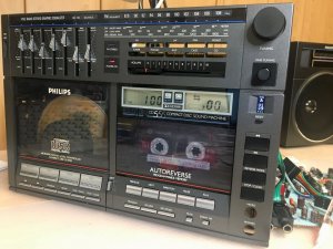
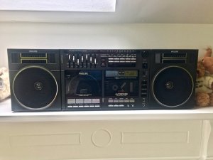
some time ago I started a restoration project of my beloved Philips 70CD555. Since than I had some serious progress. From the three machines I own I've got the first one quite easily repaired (although the FM part is not working which I noted later). Just some transistors and fusable resistors replaced. Caps need to get replaced later.
Unfortunately the second unit is a real challenge since someone used it as a donor. Pretty sure about this, because every single part failed and some things got replaced or connected the wrong. Hell, even the volume potentiometer was soldered back into the device the wrong way! Not to mention that someone moved the currency potentiometer of the cd-laser but thankfully to almost zero.
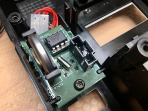
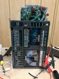
So beside fixing every panel from power supply, amplifier, cassette to cd-decoder and cd-controller I run into another huge challenge since the tape deck CPU was broken. I replaced it with an AT1284P and had to disassemble how the autoreverse tape deck has to be addressed with all the motors, gears and relays. Well right now I am pretty much done with the source code and just doing some fine tuning. Every feature is back available and some additional features are implemented like a better user interface design for programming, music search for multiple tracks etc.
Besides to get repaired I exchanged all capacitors with high quality and audio capacitors. Upgraded the OpAmps and added a Bluetooth module to act as speaker for streaming. That makes so much fun and the little bastard is working absolutely great.
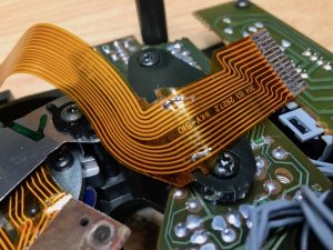
However, still need to replace the CDM2 because the one from a donor Philips CD150 is not sustainable. It sometimes fails to jump to tracks. Anyway, I already repaired the original CDM2. Took me a while to understand and to learn all those things. Just waiting to get a better gear for the tape mechanics before I disassemble it tagain.
And I have a third unit which is waiting to get repaired. Not getting bored the next months.
If someone is interested and want to get more details - have a look at my page...
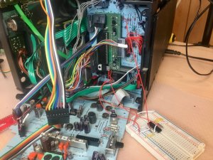
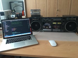
Here are some pictures...
Kind Regards,
Daniela
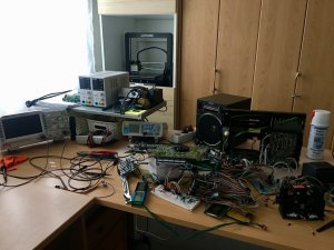
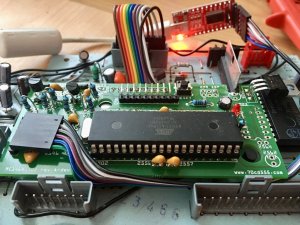


 . Had issues with the clock for the CD-Player CPU which gets also powered by the same oscillator but the new CPU is running on 16MHz and the old one on 5.7MHz. Using now two D-FlipFlops to divide the clock to 4MHz. For final tests the FlipFlop is currently outside on an experimental board.