Panasonic RX-5005 service manual

Kirill1012

New Member
Hello everyone.
Does anybody have service manual for Panasonic RX5005 ?

I did some stupid mistake when cleaning record/playback switch and did not take a photo when disassembling it for maintenance.
There are 8 sliders inside 6 - 3 contact ones and 2 - with 2 contacts. Just wanted to put it back together right without shorting the circuit.
Any help is appreciated.

Thank you !
 

Attachments

  • playrecordswitch.jpg
    playrecordswitch.jpg
    282.6 KB · Views: 11

Tinman

Member (SA)
Ok, yeah, that does suck.
servicemanuals.net looks like a similar price, $16.99 + tax.
I checked and found my Nat/Pan RX-5350's record bar pics but it's completely different from yours.
Hopefully you get it resolved.
 

Superduper

Moderator
Staff member
All of those contact are the same width so I suspect that the 2 and 3 contact feelers serves the same purpose and probably are intended for use at the 2 ends of the switch and I recommend you just fit the contacts and test the switch with the contacts in place to see if it makes any difference electrically, I suspect they will not. Service manuals typically do not give you the internal details of those switches because they were never meant to be serviced, as the switch is intended to be replaced as an assembly. However, if you feel like the service manual will provide you better guidance, you can get it from AnalogAlley.com for $13.95:

Panasonic RX-5005 /5005A service manual

As for $20 for a $30 boombox.... I feel you but that's not really here or there. After all, if the boombox was a gift to you, or you got it for $3.99 at the thrift store, or you paid $199 for a minty one off ebay, each scenario has nothing to do with the cost of the service manual.
 

goodman

Member (SA)
Service manuals typically do not give you the internal details of those switches because they were never meant to be serviced,
as the switch is intended to be replaced as an assembly.
Yes, I agree with you.
I haven't seen any mention of this information in the service manuals I have for my boomboxes.
I think the only option is to find a second boombox for spare parts.
 

caution

Member (SA)
Service manuals typically do not give you the internal details of those switches because they were never meant to be serviced

True, but it would allow you to determine how the record bar is connected to the rest of the design, possibly shedding light on which sections of the switch are single throw and which are dual (if that's indeed why there are 2- and 3-contact slider pieces).
 

Tinman

Member (SA)
SD jogged my memory.
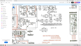
I went back and looked at the 5350 manual which has the switches internals included.
They drew all of the sliders as being only two contacts but I believe most are three but they do only contact two of the corresponding contacts at a time.
They numbered them 123123123 etc.
Meaning they all contact 1&2 when slid to the left and contact 2&3 when slid to the right.
You can verify it by putting yours partially together, manually sliding it back and forth (carefully) and seeing for yourself if they all contact the same way.
Be careful, those sliders bend very easily.

Screenshot (5).png
 

Superduper

Moderator
Staff member
True, but it would allow you to determine how the record bar is connected to the rest of the design, possibly shedding light on which sections of the switch are single throw and which are dual (if that's indeed why there are 2- and 3-contact slider pieces).
Yes, these long bar switches are basically multi-ganged switches and schematic diagrams do show all the switches but they won't be shown ganged like that in a block, they will be shown individually spread out through the circuit diagram. One would have to understand this, that the switch will typically not be represented like in it's physical form. You can figure it out with some work which pin of the switch is connected where by cross referencing the switch contacts in the schematic with adjacent circuitry based on the schematic. For example, if a particular transistor leg is connected to one of the switch pins, you can either use the PCB layout diagram to figure out where in the record bar that switch pin is physically located, or you can use a DMM using continuity mode to figure out which switch pin is connected to that point.

Essentially all I'm saying is that most service manuals aren't going to just identify everything for you, you may have to do some work on your own. I get feedback all the time on service manuals regarding how the user can't figure something out even though all the information is present that they need to determine it. This leads me to understand that not everyone is capable of tracking down a circuit even with a service manual, which is why I cautioned that the switch innards likely won't be articulated in the manner that they might expect. It usually takes work and some technical ability.
 

Superduper

Moderator
Staff member
SD jogged my memory.......
Meaning they all contact 1&2 when slid to the left and contact 2&3 when slid to the right.
You can verify it by putting yours partially together, manually sliding it back and forth (carefully) and seeing for yourself if they all contact the same way.
Be careful, those sliders bend very easily.
That's basically what I suggested, put it together and carefully test the switches individually to see if they behave like they should. I see 24 switch pins and 8 movable contact feelers, which suggests to me that there are 8 switches with 3 pins each. That's usually pretty easy to test, with each set of 3 pins, the center pin will be the common and the contact will toggle between the other 2 adjacent pins.

As for the RX-5350, that is a much higher end boombox than the RX-5005 which is a entry level boombox. In my experience, higher end devices will have more comprehensive data in their respective service manuals.
 
  • Like
Reactions: Tinman