LED's and resistors...

Status
Not open for further replies.

Superduper

Moderator
Staff member
That question can't be answered without knowing what voltage is going to be supplied to it, how it's going to be connected (series or parallel) and if series, how many.
 

btphoto

Member (SA)
They would be in parallel for sure. I'll have to check for the voltage that will be supplied to them.
 

Superduper

Moderator
Staff member
Ok. Well, LED's have very low tolerance for over-voltage so you need to determine the max voltage that the LED will see. Usually, that is when powered by AC and you should actually measure and not rely on how many batteries.

Also, if wired in parallel, each LED will require it's own resistor.
 

btphoto

Member (SA)
Ok thanks. I'll have to measure tomorrow. It's whatever voltage that is found at the speaker terminals in a new i931x It fluctuates with the volume and song, so I'll have to find the deepest loudest song and crank the volume and take my measurements then I guess, lol
 

Superduper

Moderator
Staff member
LED's have a very limited voltage operating range. For example, red LED's might begin to light at 1.6 volts, then blow at 2.2 volts. Such a narrow operating range makes them not very good for what you have in mind. Then they also only light with DC, unlike incandescents that work on AC or DC. Speaker voltage is basically a sinewave and depending on the amp design, could be AC or an AC-type sine wave that floats above ground.

Since they are cheap, I suppose you can give it a try.
 

btphoto

Member (SA)
Oh Ok. I was hoping a resistor of some sort would create a cap and limit the voltage to the LED's tolerance level.
 

Superduper

Moderator
Staff member
Resistors limit current to the LED's. It's not a straight curve on the graph but resistors will cut current not only at high voltages but at low voltages too.... see the problem?
 

baddboybill

Boomus Fidelis
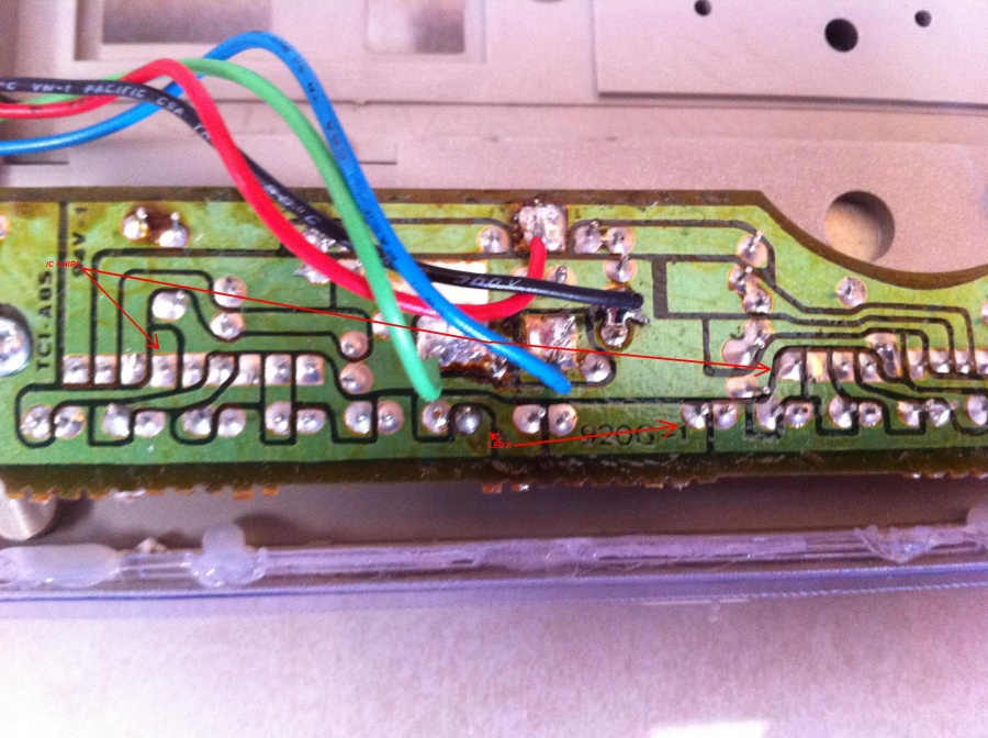
Bill This is the trace side of the led meter board from the Lasonic trc920..There is one IC chip per row of leds...so more is involved to this :huh: :hmmm: SORRY :sadno:


trc920ledboard.jpg
 

btphoto

Member (SA)
Ok cool! And I think I answered my own question in regards to the diagram without the 2 position switch:


led_blink.jpg
 

=ml=

Member (SA)
btphoto said:
Ok cool! And I think I answered my own question in regards to the diagram without the 2 position switch:


[ Image ]
You beat me to it! :-D Yep, that's exactly what I was working on. :yes:

Let us know how it turns out! This would make a cool Instructable.

Go!

=ml=
 

btphoto

Member (SA)
Will do! I just have to order some LED's I just got back from Radioshack and bought 4 of those TIP31 transistors, so I have backups, lol!
 

Superduper

Moderator
Staff member
You won't need backups. The person who designed it didn't know what to choose component wise because the TIP31 is rated at 3-amps, which is far overkill. Normal LED's only consume 20 to 25mA and at a full 12 volts, 300mW max. Normally, transistors like the TIP31 are driven by smaller "driver" transistors. Also, there is no bias voltage in this circuit so the transistor is behaving more like a switch rather than as an amp. So rather than progressively making the LED's brighter based on music transient strengths, it will likely ignore quiet passages below .7 volts or so (bias voltage). At .7 volts, the transistor begins to turn on in an active state until it reaches saturation. The TIP31's saturation voltage is only 1.8 volts so at 1.8 volts, it's full on. From that point on, it doesn't matter if the signal is 1.9 or 6.5 volts -- the result is the same. Switched full on in saturation and the LED's stay same brightness. Therefore, it's possible that at lower volumes, the LED's don't blink at all and at high volumes, they stay pretty much lit with little blinking with the music. But this is in theory only anyhow. Your mileage may vary, and there are far better ways to design such a circuit so it works with a greater range of signal strength, but it's simple and looks like it will work. Sort of.
 
Status
Not open for further replies.