Hey folks, I thought I'd share this mod with you guys. Basically, I wanted to change the standard Red and Green LED's for something a bit funkier, so I thought maybe a 'rainbow colour' effect would look pretty neat 
I did initially have difficulty finding the rectangular type LED's, and in different colours, but eventually managed to find a seller based in China (via eBay), that had something that looked like it could work. These are the LED's I got (item link >here< - mods please remove if against rules)

Took around 12 days to arrive in the mail. The total cost including shipping was approx GBP£5 for x10pcs of each colour (60pcs total), so not bad overall For this mod, I won't be using the White ones, but I might save them for something else, for example, illumination behind the cassette reels.
Next job is to get inside the unit. Luckily the PCB that holds the level indicators is a separate unit, with only around three wires connected to it, so removing the unit was fairly straight-forward (just remember to make note of the wiring).
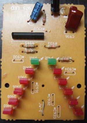
A Sanyo B1403N IC controls x5 LED's to form the level meter (the Green ones are a Power/ Stand-By indicator). The LED's opposite each other are connected in parallel to give the impression of separate Left and Right channels, but in reality they're the same. A second IC would be required to make them into Stereo level meters (another potential modification maybe).
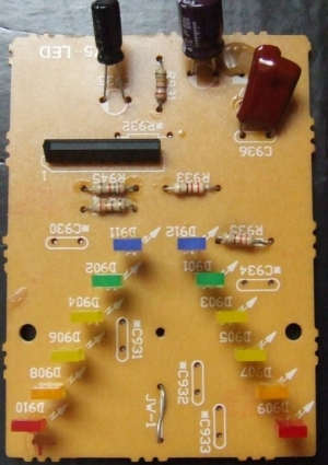
I went ahead and de-soldered the old LED's. The legs have small tabs on them so at least you know that they're all around the same height. The replacement LED's also had small tabs on them as well, but I found they could still slip through the holes in the PCB, so attention had to be paid to the height of each one. Here's the new LED's fitted:
I thought I'd replace the two electrolytic capacitors on the board as well. I'll probably do a blanket replacement of all the caps at a later date. On inspection, I noted that most of the caps on the main PCB, PSU and amplifier section seem to fall into the following (common) values: 0.47uf, 1uf, 10uf, 47uf, 100uf, 1000uf, 22uf, 220uf, 3300uf (anything around 50v will suffice).
Let's power up the unit to see what they look like:
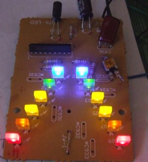
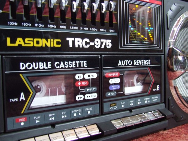
On first impressions, the Blue LED's were far too bright, completely washing out the colour from the other LED's. I figured soldering in a potentiometer (variable resistor), to set the brightness down would help things. You can see this soldered in series with R935). The same was done for the Orange LED's as these were a tad on the bright-side also.
The Green ones look a bit dim so will probably try 'borrowing' some of the power from the Blue LED's (seeing as these are the only static ones in the circuit), but for now it seems ok so I didn't bother (the picture there was taken prior to setting the Blue brightness down).
All that was left to do was re-assemble the unit and take some more photos.
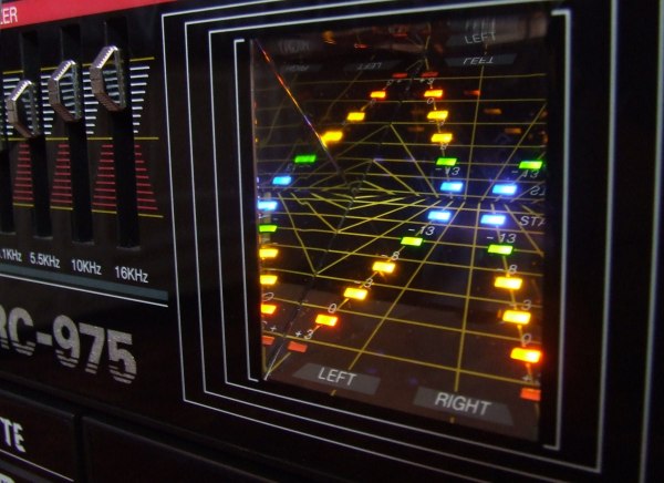
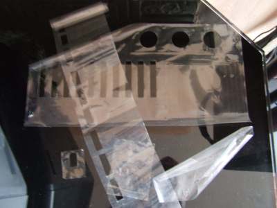
I still had the protective film over all the transfers, bar one tape door (even the voltage selector switch and rating plate still had these on), but I went ahead and peeled them off as they were starting to look a bit scruffy anyway.
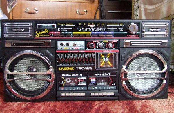
I quite like the way the LED's match the overall colour scheme of the 975 A quick once-over with some dashboard shine on the outer casing, job done.......now if I could only figure out where I left the piece of Lino!

I did initially have difficulty finding the rectangular type LED's, and in different colours, but eventually managed to find a seller based in China (via eBay), that had something that looked like it could work. These are the LED's I got (item link >here< - mods please remove if against rules)

Took around 12 days to arrive in the mail. The total cost including shipping was approx GBP£5 for x10pcs of each colour (60pcs total), so not bad overall
 For this mod, I won't be using the White ones, but I might save them for something else, for example, illumination behind the cassette reels.
Next job is to get inside the unit. Luckily the PCB that holds the level indicators is a separate unit, with only around three wires connected to it, so removing the unit was fairly straight-forward (just remember to make note of the wiring).

A Sanyo B1403N IC controls x5 LED's to form the level meter (the Green ones are a Power/ Stand-By indicator). The LED's opposite each other are connected in parallel to give the impression of separate Left and Right channels, but in reality they're the same. A second IC would be required to make them into Stereo level meters (another potential modification maybe).
I went ahead and de-soldered the old LED's. The legs have small tabs on them so at least you know that they're all around the same height. The replacement LED's also had small tabs on them as well, but I found they could still slip through the holes in the PCB, so attention had to be paid to the height of each one. Here's the new LED's fitted:

I thought I'd replace the two electrolytic capacitors on the board as well. I'll probably do a blanket replacement of all the caps at a later date. On inspection, I noted that most of the caps on the main PCB, PSU and amplifier section seem to fall into the following (common) values: 0.47uf, 1uf, 10uf, 47uf, 100uf, 1000uf, 22uf, 220uf, 3300uf (anything around 50v will suffice).
Let's power up the unit to see what they look like:

On first impressions, the Blue LED's were far too bright, completely washing out the colour from the other LED's. I figured soldering in a potentiometer (variable resistor), to set the brightness down would help things. You can see this soldered in series with R935). The same was done for the Orange LED's as these were a tad on the bright-side also.
The Green ones look a bit dim so will probably try 'borrowing' some of the power from the Blue LED's (seeing as these are the only static ones in the circuit), but for now it seems ok so I didn't bother (the picture there was taken prior to setting the Blue brightness down).
All that was left to do was re-assemble the unit and take some more photos.


I still had the protective film over all the transfers, bar one tape door (even the voltage selector switch and rating plate still had these on), but I went ahead and peeled them off as they were starting to look a bit scruffy anyway.

I quite like the way the LED's match the overall colour scheme of the 975
 A quick once-over with some dashboard shine on the outer casing, job done.......now if I could only figure out where I left the piece of Lino!


 .
.

