So, after acquiring two 931's, one with no working switches, I set out to develop some sort of solution. I couldn't have the little plastic cog duplicated professionally, as the cost was way too high ($5000 for 100 pieces). I decided to buy some mold making products and cast my own part with casting resin. I started with a craft store grade of mold and casting product, which yielded an awful result (see photos). I switched to Alumilite brand for both products and so far have been very happy with the result. I still need to install the cogs, re-assemble the switch and check for strength/durability. There-in lies the hard part. In order to slide the cog back onto the shaft, one needs to file down the lip that was pressed in at the factory. Filing it takes two minutes. The hard part is getting the cog to stay on. If you were to pull out on the shaft, say to remove a knob at a later date, it would come out of the cog gear. That's my current hold up, along with an extremely busy work schedule. The mold is also suseptable to small air bubbles, which can severely screw up the teeth in the final product. Also, I may need to make a new mold after gluing the original part. The hairline crack is somewhat duplicated in the cast piece and I'd hate for it to make a weak point in the final product.
My ultimate goal in this is to make something durable and offer it for a small fee (say, $10/cog $15/set for the time and to cover the cost of the chemicals). This would allow others (who are capable of de-soldering the switch) to fix their Lasonics. I imagine I could also repair them if the boards were mailed to me (or mailed to another technically skilled member).
Anyway, here's what I've got thus far:
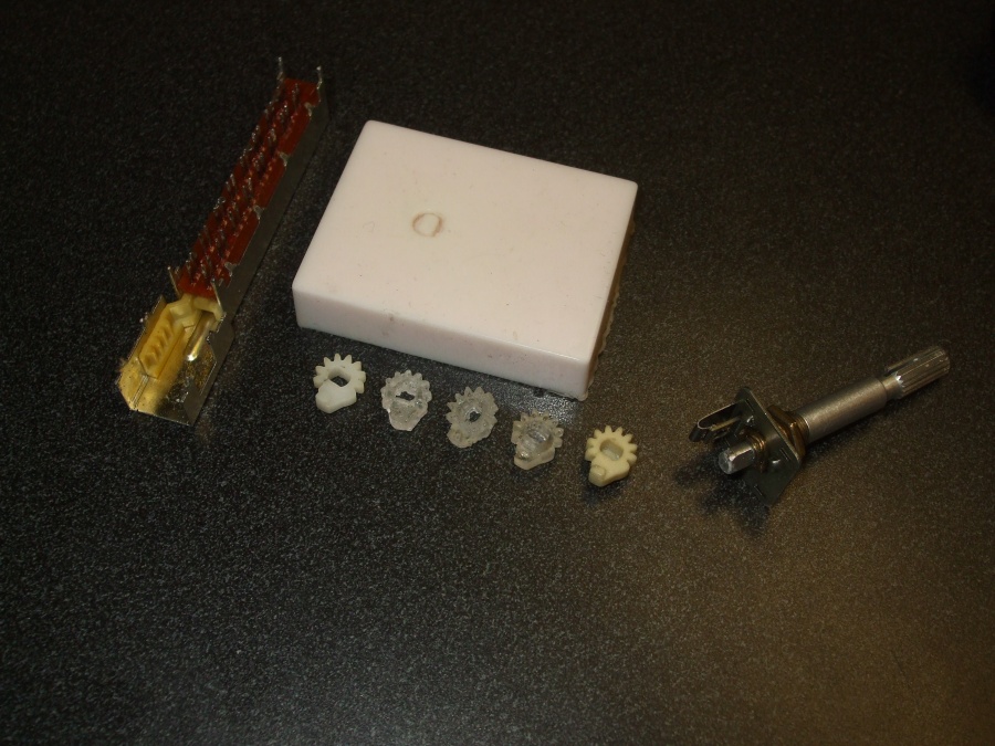
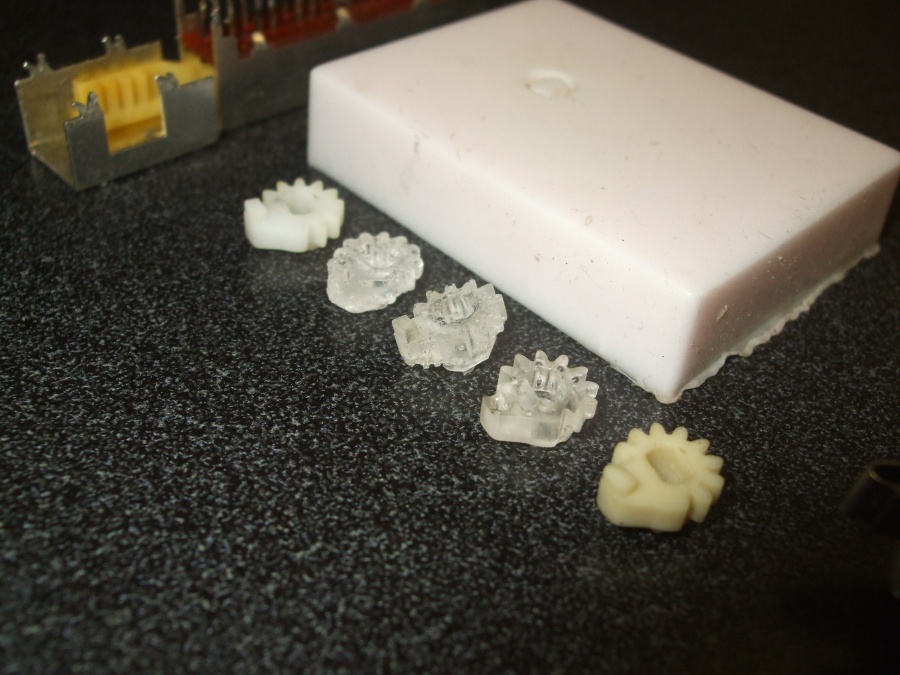
Here are all the parts I've duplicated. The first tan piece is the original. The clear version was made with the crafting chemicals. The tan version is alumilite. The alumilite mold is also seen here. It is "High Strength 2" and keeps it's shape extremely well.
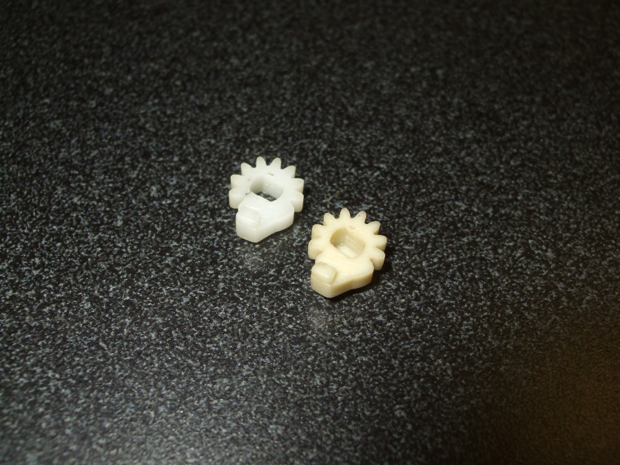
Here is the original next to the first successful cast of the new part:
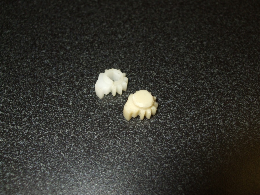
Another angle:
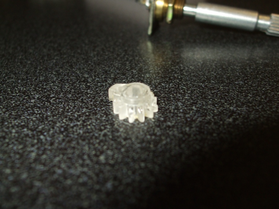
This is a part that suffered from air bubbles in the casting mix. This was the craft-grade product.
Here is the switch actuator, showing the shaft which had the original fitted and secured on. It has already been filed down in this picture.
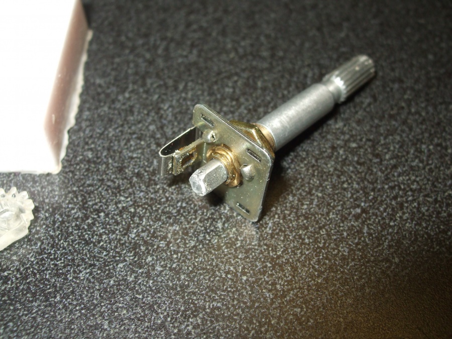
This illustrates how far the shaft pulls out with no gear attached. If it were filed better it would pull out fully. This shows that whenever you pull off a knob, you're putting a good amount of stress on the plastic part.

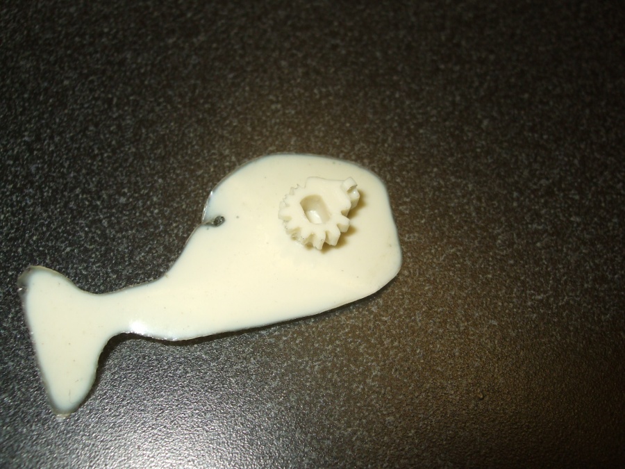
Here is a part fresh out of the mold. It isn't perfect, there are some small bubbles.
My ultimate goal in this is to make something durable and offer it for a small fee (say, $10/cog $15/set for the time and to cover the cost of the chemicals). This would allow others (who are capable of de-soldering the switch) to fix their Lasonics. I imagine I could also repair them if the boards were mailed to me (or mailed to another technically skilled member).
Anyway, here's what I've got thus far:
Here are all the parts I've duplicated. The first tan piece is the original. The clear version was made with the crafting chemicals. The tan version is alumilite. The alumilite mold is also seen here. It is "High Strength 2" and keeps it's shape extremely well.


Here is the original next to the first successful cast of the new part:

Another angle:

This is a part that suffered from air bubbles in the casting mix. This was the craft-grade product.

Here is the switch actuator, showing the shaft which had the original fitted and secured on. It has already been filed down in this picture.

This illustrates how far the shaft pulls out with no gear attached. If it were filed better it would pull out fully. This shows that whenever you pull off a knob, you're putting a good amount of stress on the plastic part.

Here is a part fresh out of the mold. It isn't perfect, there are some small bubbles.


 that's ingenious, sure hope it works


