KABOOM RV-B99 Won't retain memory, have to unplug/replug to power ON.

Status
Not open for further replies.

dinosoar

New Member
Hello. I ALWAYS have to unplug the AC cable at the wall then re-plug, in order to power up my B99. I have working remote and (10) good D cell batteries installed. The AC plug on the rear of the unit has a three prong (leg) electrical device embedded that interrupts the DC battery circuit and activates the AC power circuit if working properly. I believe this to be true. So...todays questions are (1) what is the trade name etc. of the embedded electrical 'switcher' device? (2) Does this 'switching' component affect the memory, also? (3) Does this boombox have a capacitor/s to assist the clock memory and, radio preset memory? (4) If so, is the capacitor's charging controlled by the AC socket interruption from DC to AC power? After unplug & re-plug, the remote will light up the display screen, remote will do radio auto. preset, but neither remote nor the POWER button on 'box will power the KABOOM off. You have to unplug it again....and again. ANY input from anyone would be a real bonus. Thank You for taking the time to read this, fellow members. Best Wishes, dinosoar.
 

caution

Member (SA)
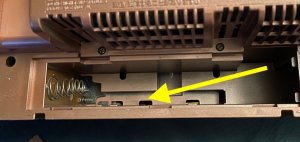
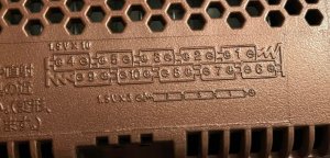
I do not own a Kaboom, but from what I'm seeing, you are missing a spot in the battery compartment for a set of three batteires (AA's?) to provide backup power.

1. It's called a switch. There are shunt springs involved, if you want to get detailed about it.
2. No.
3. No.
4. No.

Long story short:
The operator's manual indicates that there are indeed backup batteries, so check the battery compartment again for a spot to add three AA or AAA batteries.

52218886009_efd3bbfe20_b.jpg


Long story not-so-short:
The service manual seems to indicate a second Battery Source" BS2, consisting of three 1.5V batteries to make 4.5V. BS1 are the main batteries (10 cells) to make 15V:

52217521827_59f730b299_h.jpg


It says that FW603 connects to CN193. CN refers to a connector jack mounted to the board, and FW refers to a cable, or "Flat Wire" cable that has a plug on the end of it that goes into the CN jacks. This image shows the battery board, with the source of the cable carrying power from both battery sources:

52218602001_bae65fc2ca_h.jpg


As you can see, FW603 only has 4 pins, but it has 5 pins on the schematic.
Or does it?
If you look above at the schematic image, pin 5 looks to be separated on the schematic, with those heavy dashed lines indicating that it's on a different PCB. My guess is that pin 5 is wired to a tiny PCB that touches the other (positive) end of the backup battery stack. It may be this little board to the right of the main battery board:

52219054980_d0a9f4c116_h.jpg


The service manual shows all of the unit's PCBs in the manner in which they are manufactured. That is, they are arranged in a single large PCB panel, with all of the individual PCBs for the Kaboom tied together with tabs that snap apart.

It looks like pin 1 on the battery board is the left-most pin, because that goes to BS2, just like FW603 pin 1 goes to the negative side of the 4.5V battery on the schematic. It would've been helpful if they had marked BS1 and BS2 on the schematic, but nobody's perfect, LOL.

You can also see that pin 3 does not connect to anything, just like the schematic. It's just a big pad.

Following FW603 "pin 5" we can see that it goes to pin 5 of CN193 on the battery board, which actually *is* 5 pins, marked as "BP" for backup power:

52219110525_86767a85db_b.jpg


This routes over to CN191, which on the schematic accepts the cable FW601. Following this on the schematic, it goes over to pin 10 of a 13-pin connector on the amp board called CN602 and marked as "BUP" for backup power.

52217632872_9d7a82139f_c.jpg


Looking at the amp board, there is only one place this can go, and it seems to have been mis-labeled as CN603:

52217641397_7b87eb8f1b_h.jpg


This in turn connects directly to CN408 on the function amp board:

52218691573_a7da51388e_h.jpg


The main amp and function amp board seem to plug directly into each other without a cable. I see two other nearby connectors that also line up on both boards:

52219144560_24265e0144_c.jpg


From here it seems to go to the microcontroller board by way of a hard-wired cable. It goes through a diode and into a circuit marked "Back Up" and a few other places.

52218714888_f18ccdf2e2_c.jpg
 

dinosoar

New Member
Thank You to those that took the time to reply. My B-90 & B99 units, each have functioning
Hello. I ALWAYS have to unplug the AC cable at the wall then re-plug, in order to power up my B99. I have working remote and (10) good D cell batteries installed. The AC plug on the rear of the unit has a three prong (leg) electrical device embedded that interrupts the DC battery circuit and activates the AC power circuit if working properly. I believe this to be true. So...todays questions are (1) what is the trade name etc. of the embedded electrical 'switcher' device? (2) Does this 'switching' component affect the memory, also? (3) Does this boombox have a capacitor/s to assist the clock memory and, radio preset memory? (4) If so, is the capacitor's charging controlled by the AC socket interruption from DC to AC power? After unplug & re-plug, the remote will light up the display screen, remote will do radio auto. preset, but neither remote nor the POWER button on 'box will power the KABOOM off. You have to unplug it again....and again. ANY input from anyone would be a real bonus. Thank You for taking the time to read this, fellow members. Best Wishes, dinosoar.
 

dinosoar

New Member
Thanks to all of you taking the time to reply. My B-90 & B99 units, each have functioning clock memory & radio preset memory, now that I have installed 3 memory batts in each 'box. However, each unit will not 'switch' from the clock (correct time) display to operate cassette, Cd, or radio operation using either the POWER button or the remote control...unless, I unplug the AC cord, (wire, cable) from the unit rear. Is the AC socket receptacle for the AC wire considered a circuit breaker? There is a flat movable lever piece of plastic, partially exposed and vertically embedded to the AC socket (JVC, SNZ2201-001) and could said lever possibly separate the battery/battery memory circuit from the AC circuit? This ''flap' if you will, is responsible for actuation of the three leg electric switch that does the separation of AC & DC operation. The 2 image attachments may help you see of what I speak. The AC socket shows the 'movable flap' (at six o'clock)that actuates the electrical separation of the AC DC circuits. The switch (I don't know the proper name) is pictured in the image with the green PCB. (1) what is the proper name of this switch. (2) can anyone verify that this AC socket/flap/switch separates the AC & DC? Thanks, dinosoar.
 

Attachments

  • IMG_1173[1].JPG
    IMG_1173[1].JPG
    194.5 KB · Views: 3
  • IMG_1174[1].JPG
    IMG_1174[1].JPG
    152.3 KB · Views: 3
Status
Not open for further replies.