Hi guys,
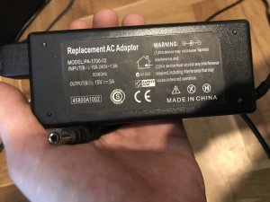
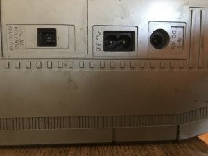
I'm doing a bluetooth modification for a old, beat up M80. It was used in a welding shop for many years. It was given to me to fix after it started acting up. It was a quick fix, it turned out the voltage switch (110-220-240V) had bad contacts and needed cleaning, later I switched to a DC adapter. During this repair I was inspired to modify the boombox with a bluetooth module. The current build is using a bluetooth module, arduino pro mini, DC-DC stepdown converter, and two relays. The build connects to the board that hosts the channel data from the radio (from my understanding) which then goes to the amplifier. Arduino is used as a bluetooth channel monitor. When the audio signal from the bluetooth module rises above a certain level the relays switch to the bluetooth audio, and when the bluetooth connection is terminated (and the bluetooth audio signal drops down again) the radio turns back on. This works quite well.
Bluetooth module


The only problem is that during testing I might have damaged the amplifier. From my measurements (using a Hantek oscilloscope) the radio output is ~ ±50 mV. I added 7 kOhm resistors in between the bluetooth output and the amplifier input, the voltage drop across these resistors would result in a ±500 mV signal (when the volume of the tethered smartphone was set to max). I initially began testing with low volume on the smartphone to be safe. Later I increased the volume, after that I started noticing volume fluctuations. Now even when the bluetooth circuit is disconnected and the radio is connected directly to the amplifier board (as originally) there are these fluctuations. Currently I'm using an audio probe to test the circuit. The radio output seems fine but I'm having a hard time probing the rest of the board beacause I don't have the board schematic.
Does anyone have the RC-M80L service manual? I only need the amplifier schematic so I can probe the circuit properly. Any questions or help is welcome.
I'm doing a bluetooth modification for a old, beat up M80. It was used in a welding shop for many years. It was given to me to fix after it started acting up. It was a quick fix, it turned out the voltage switch (110-220-240V) had bad contacts and needed cleaning, later I switched to a DC adapter. During this repair I was inspired to modify the boombox with a bluetooth module. The current build is using a bluetooth module, arduino pro mini, DC-DC stepdown converter, and two relays. The build connects to the board that hosts the channel data from the radio (from my understanding) which then goes to the amplifier. Arduino is used as a bluetooth channel monitor. When the audio signal from the bluetooth module rises above a certain level the relays switch to the bluetooth audio, and when the bluetooth connection is terminated (and the bluetooth audio signal drops down again) the radio turns back on. This works quite well.
Bluetooth module


The only problem is that during testing I might have damaged the amplifier. From my measurements (using a Hantek oscilloscope) the radio output is ~ ±50 mV. I added 7 kOhm resistors in between the bluetooth output and the amplifier input, the voltage drop across these resistors would result in a ±500 mV signal (when the volume of the tethered smartphone was set to max). I initially began testing with low volume on the smartphone to be safe. Later I increased the volume, after that I started noticing volume fluctuations. Now even when the bluetooth circuit is disconnected and the radio is connected directly to the amplifier board (as originally) there are these fluctuations. Currently I'm using an audio probe to test the circuit. The radio output seems fine but I'm having a hard time probing the rest of the board beacause I don't have the board schematic.
Does anyone have the RC-M80L service manual? I only need the amplifier schematic so I can probe the circuit properly. Any questions or help is welcome.

