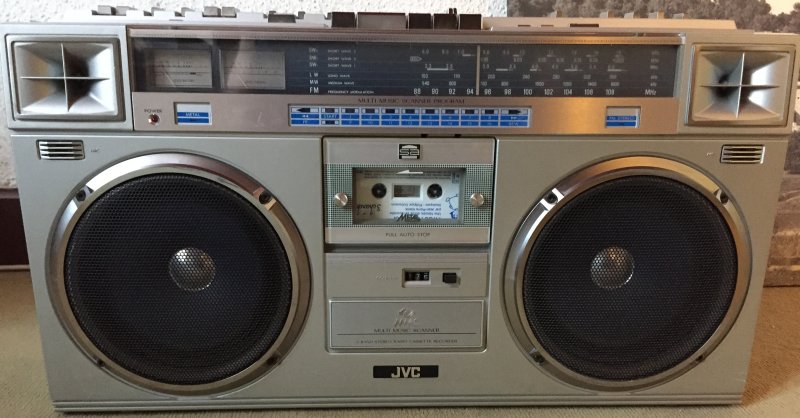
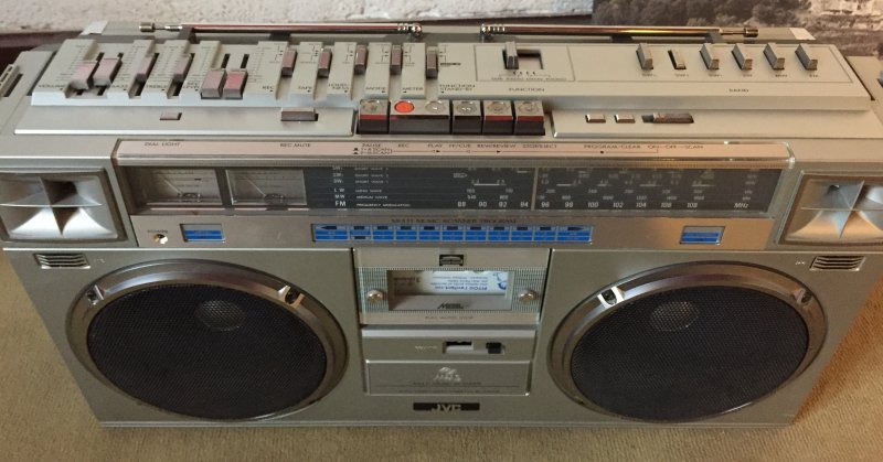
This beautiful box arrived 2 hours ago... 
I tested it, everything is working as expected, including full autostop, FM stereo reception, no cracks from potentiometers, loud sound... I recorded a song on the radio, and that's perfect too. I don't know if it has been rebelted, but I'm sure it has been opened.
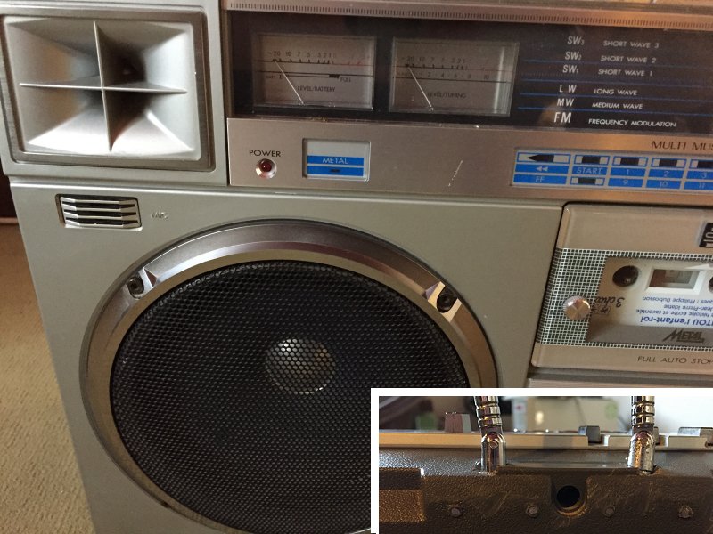
There is only one mark on the faceplate under vu-meters.
The seller was saying that it has marks, but omitted (of course) to mention that the antenna support has been repaired... Maybe I'll give him a neutral feedback (eBay). The parcel was very strong to resist the french Post treatment...
I had it at a fair price, conditon is good so .
.
After cleaning it, mods I (eventually) will do :
Led kit
Adding audio in line after the phono amplifier with a 10K resistor
Li-Po battery


The antenna broken/repaired support (will repare that later, or change the back cover ?)

Before that, I must finish to rebelt the M9998 and to mod th CX-710ME.
To be continued...

I tested it, everything is working as expected, including full autostop, FM stereo reception, no cracks from potentiometers, loud sound... I recorded a song on the radio, and that's perfect too. I don't know if it has been rebelted, but I'm sure it has been opened.
There is only one mark on the faceplate under vu-meters.
The seller was saying that it has marks, but omitted (of course) to mention that the antenna support has been repaired... Maybe I'll give him a neutral feedback (eBay). The parcel was very strong to resist the french Post treatment...
I had it at a fair price, conditon is good so
 .
.After cleaning it, mods I (eventually) will do :
Led kit
Adding audio in line after the phono amplifier with a 10K resistor
Li-Po battery


The antenna broken/repaired support (will repare that later, or change the back cover ?)

Before that, I must finish to rebelt the M9998 and to mod th CX-710ME.
To be continued...


