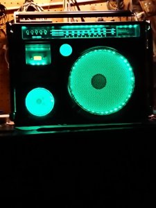
JVC RC-550 , chinese with pitch control

Status
Not open for further replies.

stynger007

Member (SA)
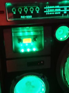
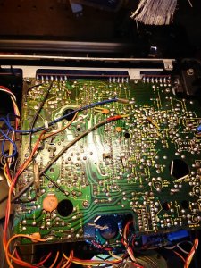
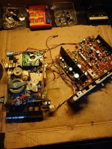
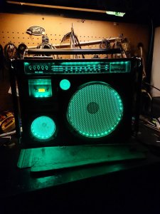
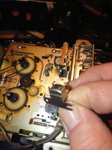
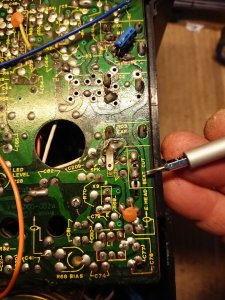
Opened er up , thick aged dust bunnies. Dude wanted Green LEDS , did his other 550 in blue. After Green install, fire her up , and ,,volume. Kicks in at about 60% , lower than that zero volume. No scratch even. Changed out belts , pressed play and muffled large. Ok. Azimuth, and dirty heads that need cleaning with a quick hit of the demagnetizer. Azimuth still off. No access through front panel, cassette door is non removable . Removed upper tier circuit board leaving wiring connected, propped it up on the speaker with a piece of cardboard to prevent shorting. Removed deck, stood her up in the chassis , pressed play and muffle regardless of adjustment. Inspecting playback head further , have never seen one this worn.

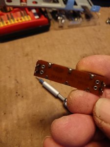
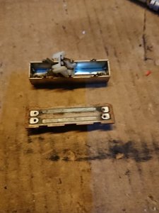
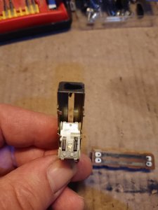
Saturday`s project: Remove volume slider , open up and clean carbon fiber and contacts. Check for resistance, top (wide open volume) should be about 50k ohms on the meter , zero volume, triple zeros and possibly a point 4. Reinstall after hopefully a successful clean proper volume control.Remove and replace worn head , adjust azimuth. Here`s a few pics from earlier today , will take more tomorrow with removal of slider, disassemble, clean, reassemble, reinstall, ohm meter ; Deck removal of head, replace, adjust azimuth with deck and circuit board propped up.

Not sure if this should be in tech talk or restoration? Mods take action if needed, thank you.
 

Attachments

  • 16192354958526378946600998487812.jpg
    16192354958526378946600998487812.jpg
    103.8 KB · Views: 11
  • DSC_1855.JPG
    DSC_1855.JPG
    264.8 KB · Views: 12
  • DSC_1856.JPG
    DSC_1856.JPG
    180.2 KB · Views: 11
  • DSC_1862.JPG
    DSC_1862.JPG
    146.4 KB · Views: 14
  • DSC_1864.JPG
    DSC_1864.JPG
    110.3 KB · Views: 13

stynger007

Member (SA)
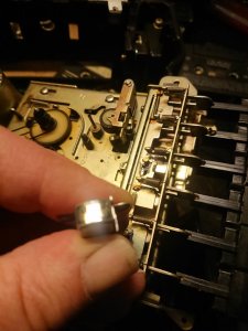
Hello everyone, a follow up to Saturday`s project: Starting with the worn head: Had a replacement here, but, it`s stereo. Looking at the wear on the head , I was able to open the static hole of the head (the round hole) by drilling , repositioned the head so it would track better..positioned the head down on the left, and the slotted adjustable side reinstalled with screw and spring. 2 Photos here, the shiny one shows the extent of wear on the head..Ideally, it should be replaced..DSC_1868.JPGDSC_1870.JPG

Next, the slider fiasco. Volume kicked in at 60% . Bass full response. Treble, sketchy. Took the volume slider off the pcb, disassembled and cleaned - but- the light portion of the carbon fiber was worn. Guck on the fingers. Reinstalled, no change on volume. Ugh. Removed treble slider, cleaned, placed in the volume position , and volume in treble position. No good. Removed bass slider, cleaned, placed in volume position, placed treble slider back in treble position, and volume slider back in bass position. Andd,, volume 100% . Bass and treble sliders offered some control. DSC_1881.JPGDSC_1876.JPGDSC_1877.JPGDSC_1879.JPG

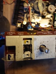
Note the first picture of this series , JVC alloted a round hole beneath the slider, possibly to allow a pot to be installed should the sliders become an issue and possibly remanufacture the metal cover plate to allow for pots instead of sliders. Gotta love forward thinking.

DSC_1882.JPG

In this pic, note the availability for Normal/Cro2 option that was never utilized- forward thinking again.

And this last pic, shows the beat/cut switch. The switch is used to tap power from the main board and switch the modded lights on and off. The resistor c75 is unsoldered on the north side using a desoldering wick, and pressed underneath using pinpoint tweezers . This disables the switch from the main circuit. You can also cut the trace , the mod is completely reversible. Attach the power lead to the switch on one side of the switch, the other lead to power tapped on the pcb red wire. The ground goes directly to the ground cluster on the pcb. (3 black wires in the cluster) . The LEDS draw little power, I use 100 ma strips .DSC_1884 copy.JPG

Most do not use beat cut and are not sure what it`s about. For those wondering about disabling the beat/cut circuit, this is used only when recording from AM radio. The oscillation between the heads and amplitude modulation can cause a feedback hum.

Have a great day everyone!
 

stynger007

Member (SA)
Great work. It seems sliders are issues on several JVCs, including M70 and RC838.
What is interesting ; is the round hole on the pcb underneath the sliders ..Is it possible JVC briefly skimped and knew that a migration to rotary controls might have been a possibility? I had an 838 , solid machine. Used it at my seasonal trailer watching movies and NHL playoffs. Green background on VU`s was different than many!
 

Reli

Boomus Fidelis
I never liked sliders, because compared to knobs they are more difficult to make small adjustments. I'm constantly overshooting and correcting myself.
The only one I really liked was the volume slider on the 838. It has nice detents in it.
 
  • Like
Reactions: stynger007
Status
Not open for further replies.