How to build-in a spectrum analyzer?

Status
Not open for further replies.

LJV

Member (SA)
Not a DIY guide but a question :)
First of all, I have no idea how signal is put trough it at all.
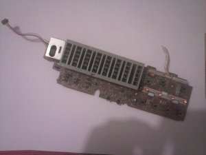
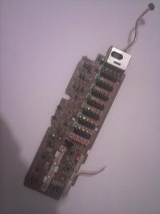
I thought to use spectrum analyzer from leftovers of Sony FH.
Cutting a rectangle hole in boombox and applying visor would be easy, but I have no clue about how to wire it and how to power it.
 

Attachments

  • CAM01066.jpg
    CAM01066.jpg
    42.7 KB · Views: 10
  • CAM01067.jpg
    CAM01067.jpg
    73 KB · Views: 9

Superduper

Moderator
Staff member
You are looking at this as if these things are modular. As if purchasing a power amp, a stereo tuner, a stereo cassette deck, equalizer and then connecting them all together with rca cables. Or, as in computers where you can purchase a new video card, hdd controller, adding firewire card to a computer without, etc.

In the previous examples, these "modules" are designed as such, with fairly standardized hookups. However, if you want to carve out a section of a boombox, then you need to understand that the circuitry would only have been designed to work with the circuitry designed in the rest of this particular boombox and may not necessarily work in another application without modification, addition of buffering circuits, etc. Otherwise, you could introduce group loops, mismatched impedances, noise, loading down of circuits, etc. This isn't to say that it may not integrate "easy" but it might also be a nightmare too. The only way to know for sure is to analyze the circuit or try it, After all, who's to say or know what the inpput impedance for that module would be, and the output impedance of the new signal source. Or whether this meter has a built in internal buffer amp, uses opamps or old fashioned transistor drivers?

Bottom line, not trying to discourage you but this is something that you'll have to figure out on your own unless someone here has already tried and hacked this using your exact same module.
 

LJV

Member (SA)
Thank you all for the replies.
I have the schematic, and it seams that S.A. just shares same PCB with manual commands and remote section - all for thr sake of compactness.
It is powered by 15V which is secondary problem.
First problem is putting the signal trough it.
I reckoned that S.A. could be attached same way as any other measuring device like voltmeter, amp meter etc.
If I figure out how to get 15V from somethibg, I could try it without building it into any bbox, just by hooking it up with headphones cable of mp3 player and connecting it to some speaker.
 

Line Out

Member (SA)
It looks like it should have the needed components on the pcb, would need a better picture and a the schematics to say for sure. It COULD work as simple as giving it the voltage it needs and then hooking it up to a summed (mono) line-level signal. I would test it with an old mp3-player IF it would be as simple as I'd hope. The level of the signal could be really low, so careful with that.

But the above is just a speculation, so... :blush:

There are some videos and other info about DIY led S.A:s, so maybe compare those to the one from Sony, and if there are any similarities, maybe those videos could be helpful?

EDIT: That eBay meter looks sweet! I immediately started to think 5 of those next to each other. Maybe the pcb should be filed a bit on the sides. Then make passive line-level filters for each one (lowpass for the lowest, bandpass for all in between and highpass for the highest).
 

caution

Member (SA)
I bet those are the driver ICs next to each bank of LEDs, maybe a BA6137 or KA2284. Both have app notes around online. Most of the parts on the board are probably filters for the band each of them is supposed to display. Eliminate those parts and focus on the rest of them and you might come close to reverse engineering it.
 

boomboxbilly

Member (SA)
Interesting project to fit a speccy analyser into your boombox :)

I just finished a little project to fit a preamp into an early model Roland Microcube, for a lady who wanted to play acoustic guitar and sing vocals through the same unit for little gigs.

Solutions were, external mixer (more bulk and complications cables) external preamp (again, possible destruction/mod of her beloved and rare acoustic or more dangly cables going to/from.

So I set about finding a clean little 9v preamp that would be faithful to an electroacoustic (the channel in the microcube sounded tacky on acoustic setting, it was hyped and is more suited to heavy metal shredders and electric blues with it’s built in cosm fx chip :)
But it was very good for vocals.

So next thing was opening it up desoldering the aux in and internally rerouting audio to the frankenstein preamp and a potentiometer, finding power without introducing ground loops and all sorts of problems, drilling a whole for the extra volume pot etc.

She was very happy with the result, clean, hiss free and just two cables to plug in, mic and frankenstein and she got a great blend in about one minute to enhance her sound. And the m/a usage will still give about 20 hours on 6 AAA.

But the crucial thing I found, was planning. Testing externally first before diving in. What Boombox are you thinking of putting it into?
15v is a bit of a sod I would say, better with 5v 8.6v 9v or 12v. Still at least it's not 48v!
 
Status
Not open for further replies.