This is how I do it in the 21st Century with excellent results.
Tools needed:
A laptop
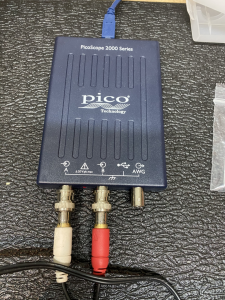
A PicoScope 2204A (PicoScope 2204A) This is a modern day oscilloscope with a lot of powerful features. We use the basic features here but this can be used for full troubelshootign and daignostics including signal generator etc.
PicoScope software installed on laptop
2x BNC to RCA adapters to connect the RCA cable to the PicoScope
1x RCA to 3.5mm jack cable
1x 3.5mm jack to 6.35mm adapter
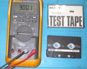
A recorded 3Khz tape
Screwdriver
15 mins of your time
1. Firstly get your software installed and test with the PicoScope so you can see something.
2. Connect the BNC adapters to the PicoScope and the RCA cable to the adapters and use the jack adapter to plug into the headphones socket if necessary.
3. Get your boombox ready to test with the 3Khz tape.
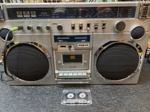
4. Make all your connections, RCA cable to PicoSCope, plugged into headphone socket, PicoScope connected to laptop and fire up the PicoScope software.
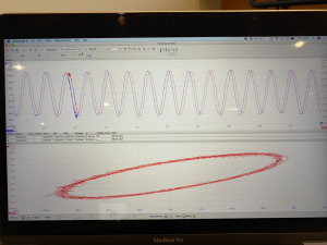
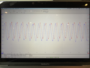
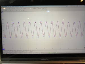
5. Play the tape, make sure you have all settings on the boombox set and function to tape. If all successfully connected, you will see your sine wave. Observe your sine waves, Red and Blue represent Left and Right channels. Here we can see they are slightly out of alignment which tells us that the azimuth on the head is off.
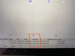
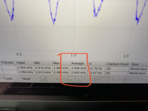
6. On this screen, in the lower left, we can also see our average speed the tape is being played at. Remember we are using a 3Khz tape so if the speed of the deck is correct we should be seeing close to 3Khz average. This tells us the deck is running slightly slow.
7. So let's sort out our sine waves first by aligning the head. Remove the cassette door or front panel if necessary to reveal the hole where the azimuth screw can be adjusted.
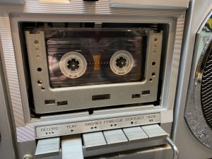
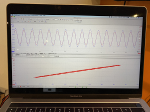
8. Adjusting this screw slightly while observing the sine waves on the PicoScope software you can align them like this to ensure the heads are aligned.
9. For the speed adjustment, some boxes have access to the motor from the rear of the unit, check if you are lucky. I had to remove the front cover for this unit and remember to reconnect the PicoScope cable to the headphone jack.
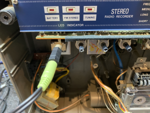
10. Luckily this motor is forward facing so access to that screw for adjusting the speed is easier than having to remove the deck.
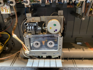
11. While playing our 3Khz tape and observing the average speed on the PicoScope software, you can adjust to get the speed close to 3Khz.
BEFORE:
AFTER:
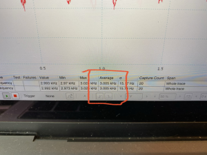
And there we have it, a beautifully dialed in deck with the correct clarity from the head and the correct speed being played.
If you need a 3Khz tape, you can purchase them or if you are confident you have a correctly dialed in deck, you can record one of your own using a tone generator app on your phone connected to your amp setup.
Hopefully this will help others for a little outlay, the benefit of having your decks dialed in perfectly is rewarding.
Tools needed:
A laptop
A PicoScope 2204A (PicoScope 2204A) This is a modern day oscilloscope with a lot of powerful features. We use the basic features here but this can be used for full troubelshootign and daignostics including signal generator etc.
PicoScope software installed on laptop
2x BNC to RCA adapters to connect the RCA cable to the PicoScope
1x RCA to 3.5mm jack cable
1x 3.5mm jack to 6.35mm adapter
A recorded 3Khz tape
Screwdriver
15 mins of your time
1. Firstly get your software installed and test with the PicoScope so you can see something.
2. Connect the BNC adapters to the PicoScope and the RCA cable to the adapters and use the jack adapter to plug into the headphones socket if necessary.

3. Get your boombox ready to test with the 3Khz tape.

4. Make all your connections, RCA cable to PicoSCope, plugged into headphone socket, PicoScope connected to laptop and fire up the PicoScope software.
5. Play the tape, make sure you have all settings on the boombox set and function to tape. If all successfully connected, you will see your sine wave. Observe your sine waves, Red and Blue represent Left and Right channels. Here we can see they are slightly out of alignment which tells us that the azimuth on the head is off.

6. On this screen, in the lower left, we can also see our average speed the tape is being played at. Remember we are using a 3Khz tape so if the speed of the deck is correct we should be seeing close to 3Khz average. This tells us the deck is running slightly slow.

7. So let's sort out our sine waves first by aligning the head. Remove the cassette door or front panel if necessary to reveal the hole where the azimuth screw can be adjusted.

8. Adjusting this screw slightly while observing the sine waves on the PicoScope software you can align them like this to ensure the heads are aligned.

9. For the speed adjustment, some boxes have access to the motor from the rear of the unit, check if you are lucky. I had to remove the front cover for this unit and remember to reconnect the PicoScope cable to the headphone jack.

10. Luckily this motor is forward facing so access to that screw for adjusting the speed is easier than having to remove the deck.

11. While playing our 3Khz tape and observing the average speed on the PicoScope software, you can adjust to get the speed close to 3Khz.
BEFORE:

AFTER:

And there we have it, a beautifully dialed in deck with the correct clarity from the head and the correct speed being played.
If you need a 3Khz tape, you can purchase them or if you are confident you have a correctly dialed in deck, you can record one of your own using a tone generator app on your phone connected to your amp setup.
Hopefully this will help others for a little outlay, the benefit of having your decks dialed in perfectly is rewarding.
Last edited:


