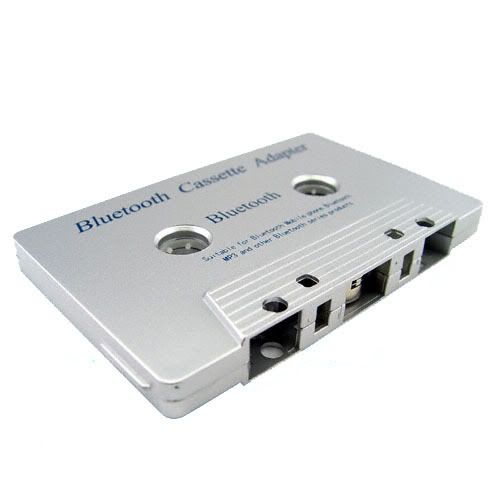
Before you decide to mod, take a look at this. This would make things eaiser but if you seriously want to mod, Proceed. If your boombox does not have LINE-IN, you might not have a choice and should get the bluetooth cassette

To blu_fuz: there ARE mp3 players with built in bluetooth . even an ipod touch has one.
Please bare with me because this is my very first tutorial . Here are the things I got:
TACTILE PUSH BUTTON SWITCH

MINI FEMALE USB SOCKET/PORT

BLUETOOTH STEREO RECEIVER FOR YOUR BOOMBOX (Gluecifer. There is a Transmitter version and a Receiver version. careful with buying this one).

3.5mm PLUG. USUALLY USED FOR HEAPHONES

MINI USB WIRE You will need 2.


FOR THOSE WHO DON'T HAVE A DEVICE THAT TRANSMITS BLUETOOTH:
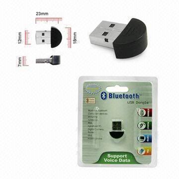
USB BLUETOOTH AD2P STEREO DONGLE TRANSMITTER (FOR computers. lets you stream sound wirelessly from a PC to a BT receiver)

ORRRR
BLUETOOTH TRANSMITTER FOR your computer's headphone jack, CD or MP3 PLAYERS (Note that some receivers look exactly
like the Transmitters.)
http://www.google.com/images?hl=en&suge ... 03&bih=566
more things you'll need: Siscors, hot glue gun, soldering iorn/gun (With a thin Tip!), flat screwdriver, knife or blade, spare wires, steady hands, magnifiers and maybe other things that you think might be needed. You can buy any stereo bluetooth receiver, But I'm posting about the one that I bought to mod the box. Same concept though...
 b7
b7
Here's the diagram After opening your stuff. Sloppy work I know.. I'm really sorry lol. I'm really hoping this doesn't look
complicated to you.

The line-in has 4 prongs but the (-) part of each channel joins. So all you really need is 3 prongs from the Line-in to
match the wires that are in the the 3.5mm cable. The cable has 3 electric wires. Match them. This might be one of the hard
parts for some of you if you can't easily detect the soldered line-in prongs on the PCB.
3.5mm cable:
Left channel -Usualy white/black (+)
Right channel -Red (+)
Ground -silver/copper (-)

The power button on the bluetooth receiver looks round..Like a tiny orange dust cap. Carefully pry it off with a blade. Here
are the Before and After images


The tactile push button switch will be used to power up the bluetooth device. It has 4 prongs. 2 of each are the same.

Solder them both. Be very careful and take your time working on the bluetooth device. When you're done. Press and hold the power button for a few seconds And it should turn on. If you do it for around 7 seconds, the LEDs will blink red and blue which means that it's searching for a Transmitting device. turn it off and hot glue the the soldered area. hot glue wont do any damage while the bluetooth device is off.

------------------------------------------------------------------------------------------------------------
MAKING A FEMALE USB SOCKET EXTENSION FOR THE CHARGER:

Again,You must have TWO mini male usb Cables. One will be cut and intergrated with the boombox and the other must be kept for charging the bluetooth device. Cut the first end which will not be needed unless you want to cut the wire in half to keep the first end
for future projects. But I recommend the second end of the cable to be longer. Inside the cable, you will find 4 wires:
RED (+)
GREEN Data
WHITE Data
BLACK (-)
The Green and White wires are not needed for this mod. On the diagram above, you will 5 pins on the female usb socket. The 4th pin is skipped So the 5th pin is PIN #4. It was stated on a pinout website (http://www.pinouts.ru). Don't get confused with the pin numbers. We'll help each other out if one of you guys aren't sure. The Red wire from the Male usb cable goes to PIN 1 and the black wire goes to the last pin (Pin #4). Ignore pins #2 and #3. Use hot glue to seal the entire pin area (optional but recommended).
--------------------------------------------------------------------------------------------------------------------------------------------
Drill holes for the button switch and the female usb socket/port

I've done a terrible job on the next pic LOL. I currently don't have the tool to make and shape holes. I even forgot what the tool is
called hahaha. I will place some sort of sheet that would hide that carved area that's around the socket (aka port). The push button switch and socket/port needs some glue too..a Strong one to keep it in place. unless the hot glue can really hold.

When that's done, place the bluetooth receiver wherever you desire and use glue to keep it in place. plug the 3.5mm plug to the 3.5mm socket which is already soldered on the bluetooth device.

If you have better ideas, use 'em because there's always a better way of getting things done.
LET ME KNOW IF I'M A BAD TEACHER


To blu_fuz: there ARE mp3 players with built in bluetooth
 . even an ipod touch has one.
Please bare with me because this is my very first tutorial
 . Here are the things I got:
TACTILE PUSH BUTTON SWITCH

MINI FEMALE USB SOCKET/PORT

BLUETOOTH STEREO RECEIVER FOR YOUR BOOMBOX (Gluecifer. There is a Transmitter version and a Receiver version. careful with buying this one).

3.5mm PLUG. USUALLY USED FOR HEAPHONES

MINI USB WIRE You will need 2.


FOR THOSE WHO DON'T HAVE A DEVICE THAT TRANSMITS BLUETOOTH:
USB BLUETOOTH AD2P STEREO DONGLE TRANSMITTER (FOR computers. lets you stream sound wirelessly from a PC to a BT receiver)

ORRRR
BLUETOOTH TRANSMITTER FOR your computer's headphone jack, CD or MP3 PLAYERS (Note that some receivers look exactly
like the Transmitters.)
http://www.google.com/images?hl=en&suge ... 03&bih=566
more things you'll need: Siscors, hot glue gun, soldering iorn/gun (With a thin Tip!), flat screwdriver, knife or blade, spare wires, steady hands, magnifiers and maybe other things that you think might be needed. You can buy any stereo bluetooth receiver, But I'm posting about the one that I bought to mod the box. Same concept though...

Here's the diagram After opening your stuff. Sloppy work I know.. I'm really sorry lol. I'm really hoping this doesn't look
complicated to you.


The line-in has 4 prongs but the (-) part of each channel joins. So all you really need is 3 prongs from the Line-in to
match the wires that are in the the 3.5mm cable. The cable has 3 electric wires. Match them. This might be one of the hard
parts for some of you if you can't easily detect the soldered line-in prongs on the PCB.
3.5mm cable:
Left channel -Usualy white/black (+)
Right channel -Red (+)
Ground -silver/copper (-)

The power button on the bluetooth receiver looks round..Like a tiny orange dust cap. Carefully pry it off with a blade. Here
are the Before and After images


The tactile push button switch will be used to power up the bluetooth device. It has 4 prongs. 2 of each are the same.

Solder them both. Be very careful and take your time working on the bluetooth device. When you're done. Press and hold the power button for a few seconds And it should turn on. If you do it for around 7 seconds, the LEDs will blink red and blue which means that it's searching for a Transmitting device. turn it off and hot glue the the soldered area. hot glue wont do any damage while the bluetooth device is off.

------------------------------------------------------------------------------------------------------------
MAKING A FEMALE USB SOCKET EXTENSION FOR THE CHARGER:

Again,You must have TWO mini male usb Cables. One will be cut and intergrated with the boombox and the other must be kept for charging the bluetooth device. Cut the first end which will not be needed unless you want to cut the wire in half to keep the first end
for future projects. But I recommend the second end of the cable to be longer. Inside the cable, you will find 4 wires:
RED (+)
GREEN Data
WHITE Data
BLACK (-)
The Green and White wires are not needed for this mod. On the diagram above, you will 5 pins on the female usb socket. The 4th pin is skipped So the 5th pin is PIN #4. It was stated on a pinout website (http://www.pinouts.ru). Don't get confused with the pin numbers. We'll help each other out if one of you guys aren't sure. The Red wire from the Male usb cable goes to PIN 1 and the black wire goes to the last pin (Pin #4). Ignore pins #2 and #3. Use hot glue to seal the entire pin area (optional but recommended).
--------------------------------------------------------------------------------------------------------------------------------------------
Drill holes for the button switch and the female usb socket/port

I've done a terrible job on the next pic LOL. I currently don't have the tool to make and shape holes. I even forgot what the tool is
called hahaha. I will place some sort of sheet that would hide that carved area that's around the socket (aka port). The push button switch and socket/port needs some glue too..a Strong one to keep it in place. unless the hot glue can really hold.

When that's done, place the bluetooth receiver wherever you desire and use glue to keep it in place. plug the 3.5mm plug to the 3.5mm socket which is already soldered on the bluetooth device.

If you have better ideas, use 'em because there's always a better way of getting things done.
LET ME KNOW IF I'M A BAD TEACHER


 . i knew there would be a better idea
  . i just dont have full knowledge on electronics and thats why i did it that way. i knew that someone here knows more than i do. thats why i said:
 but i can eliminate it with a few fixes. it was my first time and didn't have the proper tool to shape the hole like the usb port and I'm not that savvy with electronic components. I'm not yet fully prepeared. how much mAh would the regulator give? The bluetooth battery charger gives 400mAh
 That's SO cool STBNYC!!! Thanks, I'm definitely gonna try this out!!!

 Great Tutorial!