So sometime this year, another member bought a fun box which needed some tweaking. Sent it to me to work on. We agreed to extend it's capability by adding some custom stuff. I noticed that the tuner and deck wasn't really the greatest but the amp system seemed pretty decent. So I accumulated a bunch of off-the-shelf parts from China to see what I could come up with. I purchased an assortment of stuff to try and nixed the stuff that didn't work well, and kept those that did. This project took a long time, stuff from china takes forever to come.
Some of you guys that are building custom boomboxes might want to pay attention.
Anyhow, what I decided to do was splice into the tuner circuit. That way, the tuner signal would be sent to a 4-way switching assembly and sent back into the circuit. However, that leaves 3 additional available input sources. I decided to dedicate one of those for bluetooth receiver too. Additionally, the rotary switch only used 1 pole. But the switch actually had 3 poles available (or was it 4?). Anyway, rather than have the bluetooth always on, I tapped into one of the unused poles coinciding with the bluetooth receiver input position, and used that pole to switch power to the bluetooth receiver. What this means is that in every mode except bluetooth, the module will be off. When in bluetooth function position, the receiver will then be powered on.
Here is the setup doing a dry run. From left to right:
Switch block (relay)
DC C. converter (supply 5V power to bluetooth receiver)
Rotary Switch
Bluetooth receiver
DC isolator, if needed (in baggy)
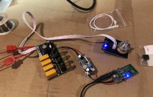
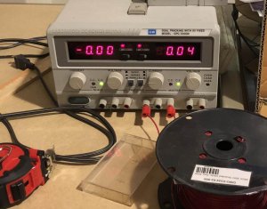
With the setup powered up with bench top supply, I observed about 40mA consumption. That includes the bluetooth. That's pretty good and consumption is small enough as to not affect anything when powered using the boombox's onboard PS.
Notice that none of the boards have any kind of mounting holes. That's simply stupid. How does any of these Chinese designers can make a board that can't be mounted? Are we supposed to glue all these boards in place. So silly. The switching block itself however is mounted via a couple of screws. I decided to tether everything together piggyback style with an interface board in between. I traced the tuner circuit and discovered that it couples to the onboard function selector through coupling caps. Perfect! I removed the caps (transplanted to my interface board). The removed caps leave 2 through-holes each which is the perfect place for in/out from add/on back to mainboard.
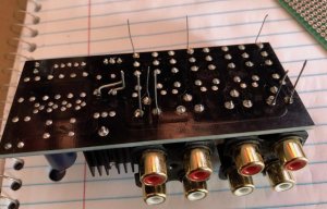
Now, to mount the interface board onto the primary switching block, I used cut leads from larger sized caps (which have thicker leads) and custom bent them into solderable standoffs. The interface board is double sided with isolated pads. That means I can install standoffs on any solder pad and would not cause any shorts.
Here is how I bent the leads and here are with a couple installed.
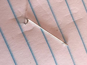
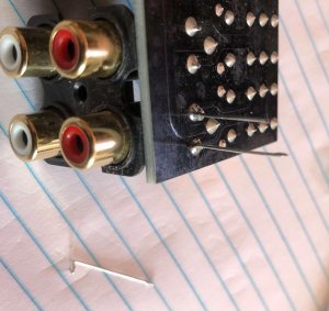
Here, I've installed enough to securely mount the interface board. Ready to add and stack boards.
-.-.-.-.-.-.-.-.-.-.-.-.-.-.-.-.-.-.-.-.-.-.-
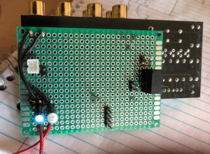
I've decided not the use the DC C converter. The system worked great except there was some ground loop hum present when system was idle between tracks. You couldn't hear it when bluetooth audio was playing but when silent, you can hear it. I wanted perfect. Also, I found that the switching block already had an onboard LM7812 regulator. So I found a 12v-in, 5v-out DC isolator which taps off of the onboard regulator. You can see it in the interface board, it's the rectangular part. Later, I found that I accidentally mounted it 180* off, which made it useless. It was too much trouble to remove and rotate the old one so I severed the traces to it and abandoned it onboard, opting instead to add another one. I lose some money but not nearly worth the effort to switch the other one around. Also, you can see the tuner coupling caps have been transplanted.
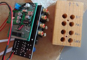
Below, you can see the bluetooth module is also stacked on as well. All boards are very secure. Notice the wood block -- that is a drill guide I made on my drill press for the RCA jacks & block mount screws. I used a thick board because the holes were fairly large 3/8 and large bits tend to wander and position vaguely. Didn't want to mess up the drilling operation into the case. On the top edge of the bluetooth module, you'll see a slide switch. That turns on the unit. I offloaded the switching functions onto the rotary switch mentioned above.
-.-.-.-.-.-.-.-.-.-.-.-.-.-.-.-.-.-.-.-.-.-.-.-
This is the best bluetooth receiver I have ever used in a project. Maybe because it's a later design but I was not impressed at all with earlier stuff I tried. I think this connects as reliably or even more so than my Aiwa EOS9 boombox.
Drill guide test fitted. Nice & snug.
Drilling holes to mount the assembly. 16 holes in total were drilled into the shell.
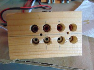
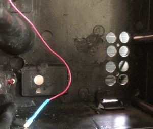
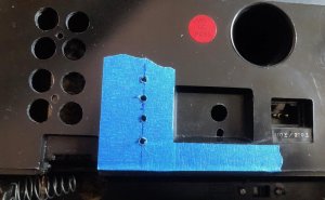
All the new boards were stuffed into the boombox. New installations on custom boombox would undoubtedly be much easier. Everything wired up and tested. All I can tell you is that it works awesome! Sometimes, adding stuff introduces other problems and noise issues. I'm glad to say I got it all worked out on this project!
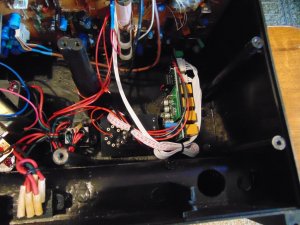
The selector has 4 led indicators to show selected function. It came with all blue LEDS. I decided to use red for the internal source/tuner mode, green for Aux-1 and Aux-2 and blue for bluetooth (obviously).
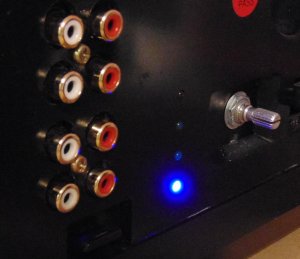
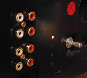
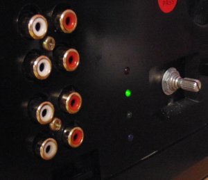
Done. Needs knob for selector but I'll leave the choice up to the owner. I temporarily printed some labels to ID the RCA's. Owner can replace them for better aesthetics if desired.
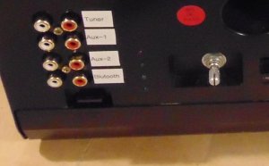
The boombox is not a secret per se but since it's not mine, I'll leave the reveal up to him, if he wants to. Anyhow, the boombox is not the focus of this thread, rather just showing that for you guys building custom boomboxes, having an input selector increases the versatility of your custom box and is not difficult to do. The selector rotary switch would ideally be mounted on the front and the RCA jacks would be mounted on the rear. Enjoy!
Some of you guys that are building custom boomboxes might want to pay attention.
Anyhow, what I decided to do was splice into the tuner circuit. That way, the tuner signal would be sent to a 4-way switching assembly and sent back into the circuit. However, that leaves 3 additional available input sources. I decided to dedicate one of those for bluetooth receiver too. Additionally, the rotary switch only used 1 pole. But the switch actually had 3 poles available (or was it 4?). Anyway, rather than have the bluetooth always on, I tapped into one of the unused poles coinciding with the bluetooth receiver input position, and used that pole to switch power to the bluetooth receiver. What this means is that in every mode except bluetooth, the module will be off. When in bluetooth function position, the receiver will then be powered on.
Here is the setup doing a dry run. From left to right:
Switch block (relay)
DC
Rotary Switch
Bluetooth receiver
DC isolator, if needed (in baggy)


With the setup powered up with bench top supply, I observed about 40mA consumption. That includes the bluetooth. That's pretty good and consumption is small enough as to not affect anything when powered using the boombox's onboard PS.
Notice that none of the boards have any kind of mounting holes. That's simply stupid. How does any of these Chinese designers can make a board that can't be mounted? Are we supposed to glue all these boards in place. So silly. The switching block itself however is mounted via a couple of screws. I decided to tether everything together piggyback style with an interface board in between. I traced the tuner circuit and discovered that it couples to the onboard function selector through coupling caps. Perfect! I removed the caps (transplanted to my interface board). The removed caps leave 2 through-holes each which is the perfect place for in/out from add/on back to mainboard.
Now, to mount the interface board onto the primary switching block, I used cut leads from larger sized caps (which have thicker leads) and custom bent them into solderable standoffs. The interface board is double sided with isolated pads. That means I can install standoffs on any solder pad and would not cause any shorts.
Here is how I bent the leads and here are with a couple installed.


Here, I've installed enough to securely mount the interface board. Ready to add and stack boards.


-.-.-.-.-.-.-.-.-.-.-.-.-.-.-.-.-.-.-.-.-.-.-
I've decided not the use the DC
Below, you can see the bluetooth module is also stacked on as well. All boards are very secure. Notice the wood block -- that is a drill guide I made on my drill press for the RCA jacks & block mount screws. I used a thick board because the holes were fairly large 3/8 and large bits tend to wander and position vaguely. Didn't want to mess up the drilling operation into the case. On the top edge of the bluetooth module, you'll see a slide switch. That turns on the unit. I offloaded the switching functions onto the rotary switch mentioned above.

-.-.-.-.-.-.-.-.-.-.-.-.-.-.-.-.-.-.-.-.-.-.-.-
This is the best bluetooth receiver I have ever used in a project. Maybe because it's a later design but I was not impressed at all with earlier stuff I tried. I think this connects as reliably or even more so than my Aiwa EOS9 boombox.
Drill guide test fitted. Nice & snug.
Drilling holes to mount the assembly. 16 holes in total were drilled into the shell.


All the new boards were stuffed into the boombox. New installations on custom boombox would undoubtedly be much easier. Everything wired up and tested. All I can tell you is that it works awesome! Sometimes, adding stuff introduces other problems and noise issues. I'm glad to say I got it all worked out on this project!

The selector has 4 led indicators to show selected function. It came with all blue LEDS. I decided to use red for the internal source/tuner mode, green for Aux-1 and Aux-2 and blue for bluetooth (obviously).


Done. Needs knob for selector but I'll leave the choice up to the owner. I temporarily printed some labels to ID the RCA's. Owner can replace them for better aesthetics if desired.

The boombox is not a secret per se but since it's not mine, I'll leave the reveal up to him, if he wants to. Anyhow, the boombox is not the focus of this thread, rather just showing that for you guys building custom boomboxes, having an input selector increases the versatility of your custom box and is not difficult to do. The selector rotary switch would ideally be mounted on the front and the RCA jacks would be mounted on the rear. Enjoy!

