Zener diode voltage?

Tinman

Member (SA)
Mar 4, 2019
518
264
63
USA
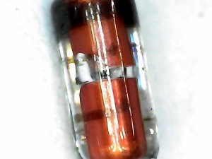
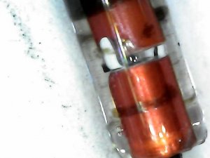
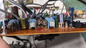
I found a zener diode to be faulty in my Vela dk-7000.
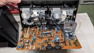
Both cassette players and all LEDs have power but no radio.
There isn't a service manual for these so I have no idea what value this is.
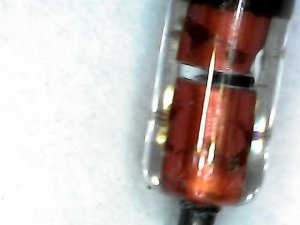
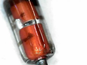
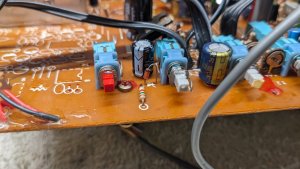
The only markings I can see is A3.
That doesn't really narrow down what the voltage and wattage should be.
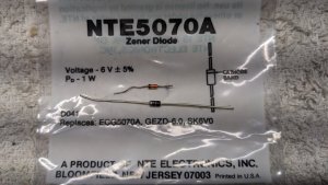
I have a couple of 6v 1W zeners on hand, should I just try one of those?
The closest resistor to it is a 470 ohm if that makes a difference.
I vowed I'd never buy another box unless I could get the service manual for it, now I remember why.
Any help would be appreciated.
 
Last edited:

Tinman

Member (SA)
Mar 4, 2019
518
264
63
USA
I'll post some pics, maybe you could figure out what's stamped on it.
I could make out the A3 with a magnifying glass.
I put it under my new "microscope" that plugs into my cell and found another marking opposite the A3.
The second character looks to be a 1 but I can't make out the first one.
This is the A3 mark:
1000001440.jpg
Here's the other:
1000001442.jpg
1000001441.jpg
1000001443.jpg
 

Tinman

Member (SA)
Mar 4, 2019
518
264
63
USA
I was thinking it looks like an 11 also.
Would that mean 11v?
From what super wrote. I searched for zener diode H11 A3.
I found a datasheet that looks like it'd be 10v .5w.
Here it is
Not sure.
 

Tinman

Member (SA)
Mar 4, 2019
518
264
63
USA
Ok, so possibly a 10 or 11 volt .5w zener.
Hopefully Super checks back in and shares his thoughts too.
 

Superduper

Member (SA)
Well, I couldn't read anything on those fuzzy photos, but I trust that you can actually see some numbers/letters on it. H11 A3 does translate to a 10.1 volt zener so I suppose it's worth a try. If you have another such diode onboard somewhere with the same markings, you can test it to confirm. Otherwise, it's "probably" a 10.1v device. Because voltage regulators gets it's control voltage from the zener diode, try to get the same voltage (10.1v). Theres method to the madness regarding the weird fractional numbers because they are factoring voltage drop in the regulator. With a 0.6V voltage drop across the transistor, this means that a 10.1V zener will translate to a 9.5V output from the regulator.
 

Tinman

Member (SA)
Mar 4, 2019
518
264
63
USA
There are no other zener diodes, just 5 regular ones.
I'll have to order some and see how it goes.
This box is a royal pita to work on.
Other than the antenna wire there are absolutely no plugs so I had to desolder the motors, take off the leaf switches and the heads to seperate the cassette players from the board.
Then you have to contend with two led boards, the eq board and other things flopping around every time you flip it from one side to the other.
Thanks for the input guys.
 

Tinman

Member (SA)
Mar 4, 2019
518
264
63
USA
Here's a shot when I first opened it up.
The zener is way up underneath the right player near the power button.
1000001297.jpg
 

Tinman

Member (SA)
Mar 4, 2019
518
264
63
USA
The other problem I'm having with this box is both motors are running fast.
Adjusting them helps but even on the slowest setting it still sounds like I'm listening to a chipmunks cassette.
The motors are both Sankyo m9h12u18-3.
They're 12v motors but there's 17 volts when running.
They have four solder connections.
From what I understand, the inner two are the neg and pos while the outer two are listed as low speed and high speed.
I usually deal with two wire motors so I'm confused about what the others do.
I've never had this problem and am not sure how to slow them down.
Anyone have any ideas?
 

Tinman

Member (SA)
Mar 4, 2019
518
264
63
USA
Here's a pic of one of mine.
The 1 and 4 are there because where the cable goes through the board, there's a 1 and 4 printed so I wanted to make sure I reinstall them correctly.
1000001447.jpg
 

Radio raheem

Member (SA)
May 13, 2009
4,971
922
113
uk
The other problem I'm having with this box is both motors are running fast.
Adjusting them helps but even on the slowest setting it still sounds like I'm listening to a chipmunks cassette.
The motors are both Sankyo m9h12u18-3.
They're 12v motors but there's 17 volts when running.
They have four solder connections.
From what I understand, the inner two are the neg and pos while the outer two are listed as low speed and high speed.
I usually deal with two wire motors so I'm confused about what the others do.
I've never had this problem and am not sure how to slow them down.
Anyone have any ideas?
is there an adjustable vr on the main board if so replace it with the correct one.....this is common place with super jumbos....forget the actual motor for now and check
 

Tinman

Member (SA)
Mar 4, 2019
518
264
63
USA
The speed control is for high speed dubbing. Maybe there's an issue with that circuit?
Ok, that makes sense.
I just looked at the front and sure enough, there's a tape speed control, duh.
I may have had it all the way to the right.
Can it be that simple?
Hopefully that's all it is.
1000001448.jpg
 

Tinman

Member (SA)
Mar 4, 2019
518
264
63
USA
is there an adjustable vr on the main board if so replace it with the correct one.....this is common place with super jumbos....forget the actual motor for now and check
That's what I originally thought it might be.
There's a T1 and T2 and they are in both 4 wire paths to the motors.
Hopefully I just had the switch in the wrong position.
1000001446.jpg
 

Radio raheem

Member (SA)
May 13, 2009
4,971
922
113
uk
That's what I originally thought it might be.
There's a T1 and T2 and they are in both 4 wire paths to the motors.
Hopefully I just had the switch in the wrong position.
View attachment 57790
i would check them for resistance and change both if not if not working......they differ from the jumbos in that the jumbos have cheap yellow plastic ones........they need to be the correct ohms etc
 
Last edited:
  • Like
Reactions: Tinman