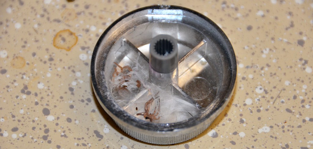
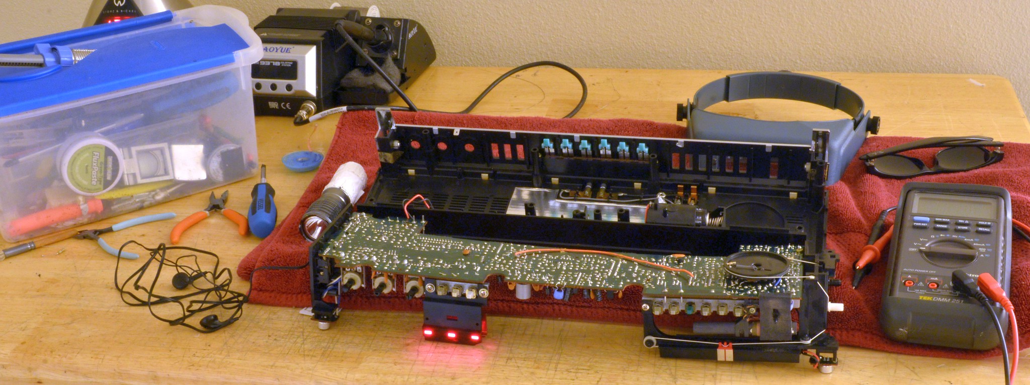
I picked up this fella over two years ago and thought I'd finally see if I can figure out what's going on. It's an extremely rare red version of the RT-S653/Bombeat DM-02. The only other photo I've been able to find is on Jen's boombox database. The thing uses the same volume pot as the M90, and also like the M90 and others it uses conductive ink for wiring and printed carbon for resistors on the top side of the board.
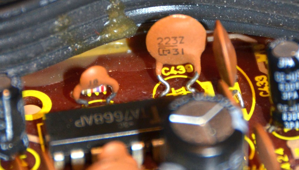
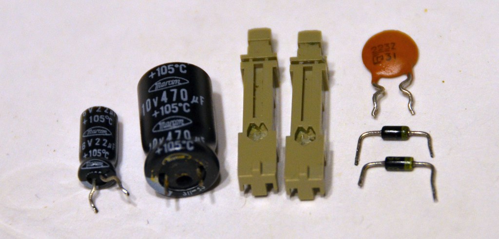
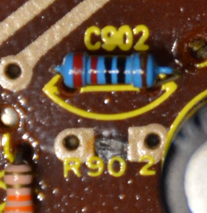
It's in a coma. When you turn it on, you get a click from the switch bounce and the quietest hiss you can possibly detect with your ear right up to the speaker, no matter what the volume is set to. After checking some voltage levels on the amp chip, it actually checked out okay. It seemed to be at least making super-quiet hiss and not silence, so I checked all the diodes. All except for two of them came up with acceptable voltage drops, both 3.3V zeners. I yanked out one side of them to get a solid reading. Yep, they're really dead. New 3.3V zeners were installed, but still in a coma.
I took a closer look at the area of the circuit where the dead diodes were. They're connected to an NPN transistor, Q901, that ties directly to the DC input jack. The datasheet says it's an amplifier. Hmm. Well, I'm lacking amplification, so maybe someone plugged in the wrong polarity into the DC jack and fried the diodes AND Q901? The only other way to power it is C cells, so I figured that may be what happened. The power LED doesn't even come on and it's right on the other side of Q901. Fishy stuff.
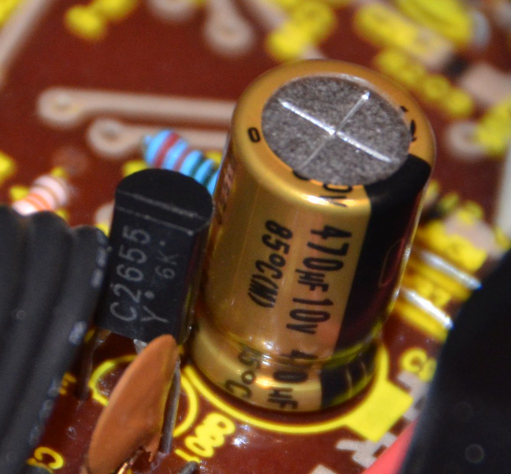
So I pulled out Q901, verified the pin order (ECB) and stuck it in the transistor checker on my multimeter and got no gain at all. Zee-ro. I tested a brand new spare NPN transistor of another type and got a gain within the specced range on its datasheet, so I know the meter works. No match in my pile of spares, so ebay to the rescue. They showed up today, but the package felt a lot heavier than it should have for their tiny size. Sure enough, the seller sent me 2SC2665 instead of 2SC2655, which are about five times larger than the correct ones. Woops. Honest mistake by an honest seller. The right ones ship tomorrow.
The belts were also a licorice factory inside, so I measured their size with some wire and found some good replacements from a VCR I tore apart recently, and if you've ever seen a VCR belt, they're BEEFY! All the pulleys were large enough to accept them, no clearance issues, so done and done.
When I popped the knobs and caps off, I unknowingly destroyed the locking mechanism inside the two pushbutton switches for the stereo modes. As it turns out, if you leave them in the engaged position, pulling on the shaft is very, very bad.
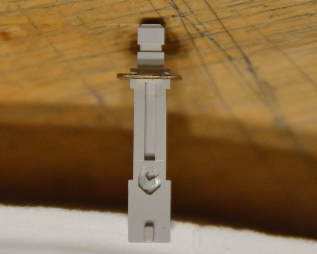
I went through my spare switches and found one match, although it had shorter leads. Not a problem, as it turns out it's the easiest switch I've ever disassembled, you only have to disengage a single tab in the back and it all comes apart. All I need is the shaft anyway.
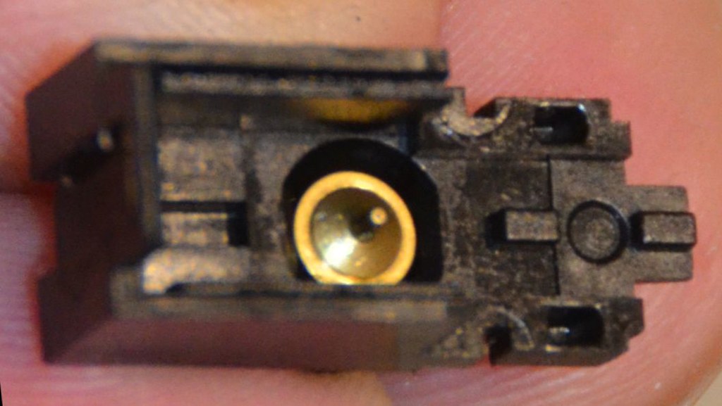
In the top of the switch case there is a spring-loaded brass pin that swivels left and right (up and down is fixed) and is centered over the track. I took a couple of pictures at different angles so the slopes in the groove floor can be seen. When the switch is in the disengaged position, the pin is sitting at the south end in a pit.
When you press in the button to engage it, the pin moves up the right side of the track, which slopes up. it falls over the cliff in the northeast corner, and then as you let go, it falls over another cliff and settles into the pit at the top center. It's at this engaged position that any pulling on the shaft will make the pin snap the center plastic piece clean off, as shown. It happened when I pushed a screwdriver into their caps from behind to pop them off.
Finally, pushing the button again to disengage it moves the pin over the cliff and into the pit in the northwest corner, so when you let go, the pin goes down the left side of the track and over the last cliff in the southwest corner, settling back into the south end.
Unfortunately I broke two of them, and I could only find one extra in my pile of spare switches. It's nearly impossible to find replacement switches based on the switch manufacturer, in this case it's SMK, and this doesn't even seem to have a part number on it, possibly because it was a custom version made specifically for Toshiba. They have a part number for it, but no dice there.
Then, I remembered that the plastic cap was still on the spare I found, and it said "POWER" so I tried to figure out which tape deck I tore that out of. I zoomed in on the pic of it I took before tearing it down and found it, a Sony TC-FX170. A cross-reference turned up four more Sony tape decks that used it, so off to ebay. I found some decks I could have paid upwards of $30 all told to get, but then I found that someone had torn down one of them and was selling just the power switch board for a few bucks. Yes please!
I was hoping to take care of the transistor this weekend as I waited for the new switch to show up, but due to seller error things will be on hold for a bit. More to come!


It's in a coma. When you turn it on, you get a click from the switch bounce and the quietest hiss you can possibly detect with your ear right up to the speaker, no matter what the volume is set to. After checking some voltage levels on the amp chip, it actually checked out okay. It seemed to be at least making super-quiet hiss and not silence, so I checked all the diodes. All except for two of them came up with acceptable voltage drops, both 3.3V zeners. I yanked out one side of them to get a solid reading. Yep, they're really dead. New 3.3V zeners were installed, but still in a coma.
I took a closer look at the area of the circuit where the dead diodes were. They're connected to an NPN transistor, Q901, that ties directly to the DC input jack. The datasheet says it's an amplifier. Hmm. Well, I'm lacking amplification, so maybe someone plugged in the wrong polarity into the DC jack and fried the diodes AND Q901? The only other way to power it is C cells, so I figured that may be what happened. The power LED doesn't even come on and it's right on the other side of Q901. Fishy stuff.
So I pulled out Q901, verified the pin order (ECB) and stuck it in the transistor checker on my multimeter and got no gain at all. Zee-ro. I tested a brand new spare NPN transistor of another type and got a gain within the specced range on its datasheet, so I know the meter works. No match in my pile of spares, so ebay to the rescue. They showed up today, but the package felt a lot heavier than it should have for their tiny size. Sure enough, the seller sent me 2SC2665 instead of 2SC2655, which are about five times larger than the correct ones. Woops. Honest mistake by an honest seller. The right ones ship tomorrow.
The belts were also a licorice factory inside, so I measured their size with some wire and found some good replacements from a VCR I tore apart recently, and if you've ever seen a VCR belt, they're BEEFY! All the pulleys were large enough to accept them, no clearance issues, so done and done.
When I popped the knobs and caps off, I unknowingly destroyed the locking mechanism inside the two pushbutton switches for the stereo modes. As it turns out, if you leave them in the engaged position, pulling on the shaft is very, very bad.
I went through my spare switches and found one match, although it had shorter leads. Not a problem, as it turns out it's the easiest switch I've ever disassembled, you only have to disengage a single tab in the back and it all comes apart. All I need is the shaft anyway.
In the top of the switch case there is a spring-loaded brass pin that swivels left and right (up and down is fixed) and is centered over the track. I took a couple of pictures at different angles so the slopes in the groove floor can be seen. When the switch is in the disengaged position, the pin is sitting at the south end in a pit.
When you press in the button to engage it, the pin moves up the right side of the track, which slopes up. it falls over the cliff in the northeast corner, and then as you let go, it falls over another cliff and settles into the pit at the top center. It's at this engaged position that any pulling on the shaft will make the pin snap the center plastic piece clean off, as shown. It happened when I pushed a screwdriver into their caps from behind to pop them off.
Finally, pushing the button again to disengage it moves the pin over the cliff and into the pit in the northwest corner, so when you let go, the pin goes down the left side of the track and over the last cliff in the southwest corner, settling back into the south end.
Unfortunately I broke two of them, and I could only find one extra in my pile of spare switches. It's nearly impossible to find replacement switches based on the switch manufacturer, in this case it's SMK, and this doesn't even seem to have a part number on it, possibly because it was a custom version made specifically for Toshiba. They have a part number for it, but no dice there.
Then, I remembered that the plastic cap was still on the spare I found, and it said "POWER" so I tried to figure out which tape deck I tore that out of. I zoomed in on the pic of it I took before tearing it down and found it, a Sony TC-FX170. A cross-reference turned up four more Sony tape decks that used it, so off to ebay. I found some decks I could have paid upwards of $30 all told to get, but then I found that someone had torn down one of them and was selling just the power switch board for a few bucks. Yes please!
I was hoping to take care of the transistor this weekend as I waited for the new switch to show up, but due to seller error things will be on hold for a bit. More to come!


") And who doesn't like chocolate?
And who doesn't like chocolate?