Hi all, checked all posts before posting this one, looking for some advice for this box of potential booms.. in return I've been taking photos and notes and intend to write up and post a strip-down, minor service, repair, reassembly and restoration post for it, could be useful for someone one day!
I rescued it from a skip from next door, with permission, but it had spent a night outside. Left it in a warm room for a couple of days and opened it to check for moisture before powering up.
Downloaded the service manual, which is sublime.
On power up everything was working but the volume is very attenuated on both channels, from both the radio and tape deck, and this is its problem.
Also with the volume sliders set high-ish to max, mode selector switch set to high and tone controls set to mid, the integrated speakers start 'fizzing' rather than clipping (still very low vol), the same happens listening to both the headphone socket and when connecting external speakers. There is also the same 50Hz mains hum at this 'elevated' volume level at all outputs. Both VU meters look equal in signal and gain.
On @docs advice from my intro post, internals were blown through to expel dust and detritus, all the pots, sliders, external audio connectors, record bar etc were cleaned in-situ with a quick dry contact cleaner, actuated lots and lots of times and left to dry - from the circuit schematics it's clear that any external connectors are connected in switch-over configurations, so it's important that these are all clean although they all look clear and clean of oxidisation already.
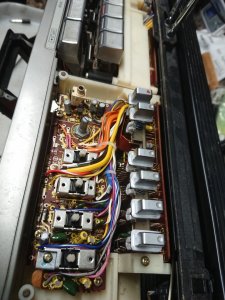
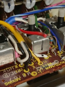
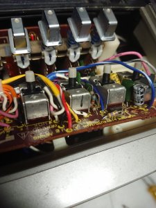
Using the service manual I stripped Ginny the GF down (by this time we'd spent considerable time together getting intimate so it only seemed right to assign a moniker) to get access to the circuit assembly. Component side there are no leaky or bulging electrolytic capacitors, no silicon burning signs or smells, no sign of ingress etc and the same on the solder side - no signs of pcb cracks or dry solder joint's and all the conductive tracks look good.
Reassembled and she does sound better and more crisp than when I started, but still with the same low level volume.
I looked at the power supply output at the pcb end next on an oscilloscope - bearing in mind the mains hum and the attenuated speaker volumes being the same on both channels. This was an expected 15.5 - 16 volts dc with about a 200mV ripple, seemed reasonable. Without immediate access to a pile of D cell batteries I happened to have a decent quality 2.5 amp switch mode psu, so disconnected the ac mains supply and clipped the external psu to the back of the dc input connector on Ginny, exactly the same poor results.
So the issue HAS to be related to a block directly connected to both channels, hence suspecting the power supply. I guess the next port of call is checking supply rails and bias voltages to all the IC's and transistors on the 'scope rather than the DMM. On the plus side whoever designed its function, form and assembly was a genius - such a pleasure to work on and has to be something simple!
Thanks for reading this far, any suggestions gratefully received.
Linz
I rescued it from a skip from next door, with permission, but it had spent a night outside. Left it in a warm room for a couple of days and opened it to check for moisture before powering up.
Downloaded the service manual, which is sublime.
On power up everything was working but the volume is very attenuated on both channels, from both the radio and tape deck, and this is its problem.
Also with the volume sliders set high-ish to max, mode selector switch set to high and tone controls set to mid, the integrated speakers start 'fizzing' rather than clipping (still very low vol), the same happens listening to both the headphone socket and when connecting external speakers. There is also the same 50Hz mains hum at this 'elevated' volume level at all outputs. Both VU meters look equal in signal and gain.
On @docs advice from my intro post, internals were blown through to expel dust and detritus, all the pots, sliders, external audio connectors, record bar etc were cleaned in-situ with a quick dry contact cleaner, actuated lots and lots of times and left to dry - from the circuit schematics it's clear that any external connectors are connected in switch-over configurations, so it's important that these are all clean although they all look clear and clean of oxidisation already.
Using the service manual I stripped Ginny the GF down (by this time we'd spent considerable time together getting intimate so it only seemed right to assign a moniker) to get access to the circuit assembly. Component side there are no leaky or bulging electrolytic capacitors, no silicon burning signs or smells, no sign of ingress etc and the same on the solder side - no signs of pcb cracks or dry solder joint's and all the conductive tracks look good.
Reassembled and she does sound better and more crisp than when I started, but still with the same low level volume.
I looked at the power supply output at the pcb end next on an oscilloscope - bearing in mind the mains hum and the attenuated speaker volumes being the same on both channels. This was an expected 15.5 - 16 volts dc with about a 200mV ripple, seemed reasonable. Without immediate access to a pile of D cell batteries I happened to have a decent quality 2.5 amp switch mode psu, so disconnected the ac mains supply and clipped the external psu to the back of the dc input connector on Ginny, exactly the same poor results.
So the issue HAS to be related to a block directly connected to both channels, hence suspecting the power supply. I guess the next port of call is checking supply rails and bias voltages to all the IC's and transistors on the 'scope rather than the DMM. On the plus side whoever designed its function, form and assembly was a genius - such a pleasure to work on and has to be something simple!
Thanks for reading this far, any suggestions gratefully received.
Linz

")
 (eternally optomistic)