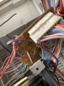
Sanyo m-x650k cassette belts, restoration

docs

Member (SA)
Jun 26, 2010
2,558
381
83
52
United Kingdom
OK lets slow down.
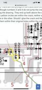
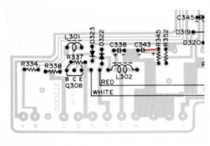
The more detailed picture shows that for number 4 we would be jumping to the same side of the board.
Without that black wire you put in place, is there continuity between those two points anyway? If so, remove the wire for now.
Don't forget, we are jumping wires across the crack to provide connectivity which is broken.

Personally, I would get the board straight and glued with something supporting it across both sides first (matchsticks) and leave glueing directly across the crack for now.
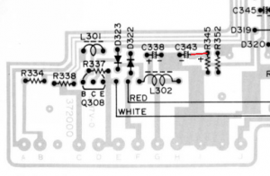
The reason I would glue it is so that we can jump this number 3 by simply replacing the capacitor for a new one (of the exact same value) and use the longer capacitor leg to go to the leg of resistor R345 like below.
We can then deal with the other leg of R345 separately to check it is connected.
Once we have everything in place and as it should be, we can worry about the disconnected wire.
1591948228801.png
 
  • Like
Reactions: Jboulukos

Jboulukos

Member (SA)
May 25, 2020
166
20
18
Cali, Colombia
I accidentally bought some bs epoxy and will go tomorrow to get the 2 part epoxy from the reputable homecenter store that is the Colombian equivalent to Home Depot.
 

Jboulukos

Member (SA)
May 25, 2020
166
20
18
Cali, Colombia
OK lets slow down.
The more detailed picture shows that for number 4 we would be jumping to the same side of the board.
Without that black wire you put in place, is there continuity between those two points anyway? If so, remove the wire for now.
Don't forget, we are jumping wires across the crack to provide connectivity which is broken.

Personally, I would get the board straight and glued with something supporting it across both sides first (matchsticks) and leave glueing directly across the crack for now.
The reason I would glue it is so that we can jump this number 3 by simply replacing the capacitor for a new one (of the exact same value) and use the longer capacitor leg to go to the leg of resistor R345 like below.
We can then deal with the other leg of R345 separately to check it is connected.
Once we have everything in place and as it should be, we can worry about the disconnected wire.

View attachment 49490
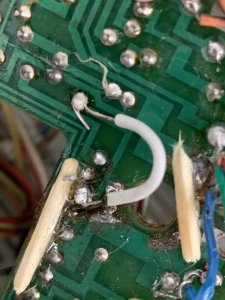
I just epoxied two match sticks to the front of the board and will place one on the other side where there is room off to the right side.
060CDDFC-53BC-49FC-AA74-F45DA27B6625.jpeg
 

Jboulukos

Member (SA)
May 25, 2020
166
20
18
Cali, Colombia
OK lets slow down.
The more detailed picture shows that for number 4 we would be jumping to the same side of the board.
Without that black wire you put in place, is there continuity between those two points anyway? If so, remove the wire for now.
Don't forget, we are jumping wires across the crack to provide connectivity which is broken.

Personally, I would get the board straight and glued with something supporting it across both sides first (matchsticks) and leave glueing directly across the crack for now.
The reason I would glue it is so that we can jump this number 3 by simply replacing the capacitor for a new one (of the exact same value) and use the longer capacitor leg to go to the leg of resistor R345 like below.
We can then deal with the other leg of R345 separately to check it is connected.
Once we have everything in place and as it should be, we can worry about the disconnected wire.

View attachment 49490
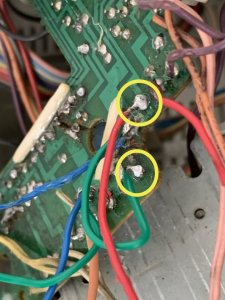
Backside circuit board match stick epoxied in place. The two front sticks that I epoxied yesterday have held up great and now the circuit board is stable and easier to work on. Tomorrow I’m going to complete the 1-6 jumper wires.
673DED20-8E12-4AFA-A929-0A77B998C87B.jpeg
 

docs

Member (SA)
Jun 26, 2010
2,558
381
83
52
United Kingdom
Looking good.
Remember to follow the tracts and determine what is on one side and the other.
For that capacitor take care as above you need to extend the leg to reach to the other side of the crack.
 
  • Like
Reactions: Jboulukos

Jboulukos

Member (SA)
May 25, 2020
166
20
18
Cali, Colombia
Looking good.
Remember to follow the tracts and determine what is on one side and the other.
For that capacitor take care as above you need to extend the leg to reach to the other side of the crack.
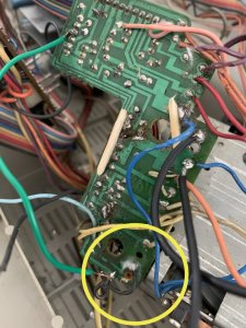
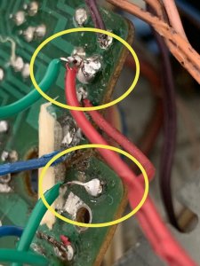
Thanks for the support and guidance. I’m usually pretty handy with projects but this is tough! I’ve rebuilt my 78 datsun carburetor etc... I’m actually having difficulty soldering the jumps. I am using 60/40 solder with a super cheap 30 watt Chinese soldering iron. I obtained some new smaller gauge solid wire to complete all the jumps. I am having difficulty with soldering a jump wire to a point that already has a wire from somewhere else. If it’s a metal end from a capacitor or something stable on the other side, I am fine soldering a wire to it, but I can’t seem to solder a jumper to a point that already has a wire on the same side. I heat it up and the existing wire falls out and then I’m left with two wires to attach to the same hole. I will show you in a pic. Not sure if I messed up the board or not. The black wire was there already and I was replacing the old jump wire with a new one. But the black and the new green are both out and I can’t seem to figure out how to get a good solder with just two hands. I’m not sure if I burnt the hole in the board. Any guidance is much appreciated. I’m trying my best to get this right. 14776401-543A-480E-8ED1-F0D9F5B3DA5B.jpeg
 

docs

Member (SA)
Jun 26, 2010
2,558
381
83
52
United Kingdom
Yes the solder pad has tore away from the tract.
Its recoverable but to be honest, we need someone who can solder to a high standard and who can make this good. They would scratch back some of the top surface of that tract and solder to it and glue it in place.
If you feel confident enough, get a better soldering iron.
To solder two wires to one point, twist the ends together and solder as one with plenty of solder.
 
  • Like
Reactions: Jboulukos

Jboulukos

Member (SA)
May 25, 2020
166
20
18
Cali, Colombia
Yes the solder pad has tore away from the tract.
Its recoverable but to be honest, we need someone who can solder to a high standard and who can make this good. They would scratch back some of the top surface of that tract and solder to it and glue it in place.
If you feel confident enough, get a better soldering iron.
To solder two wires to one point, twist the ends together and solder as one with plenty of solder.
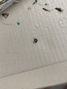
Great advice. I can certainly twist the two wires together and solder it. I don’t know why I didn’t think of that. I think I am going to ask my girlfriend to hold the twisted wires in place. I have the solder pad, can it be glued in place. What can I do to repair the solder pad? I feel confident, just need to execute. I have the pad that peeled off. E4581C67-0A3F-4022-9762-1CC8BC4A3F54.jpeg
 

Jboulukos

Member (SA)
May 25, 2020
166
20
18
Cali, Colombia
I can hire someone to help solder it but that doesn’t mean they will make the cassette deck work. I’m a bit bummed that the circuit board was so trashed from the start. I’m going to research how to repair the detached solder pad.
 
Last edited:

docs

Member (SA)
Jun 26, 2010
2,558
381
83
52
United Kingdom
The pad is just a small piece of copper? Attached to that tract to provide connectivity to a solder point and often a component.
On the board, you can gently scratch back the top layer which covers the metal tract to reveal the surface which can then be soldered to. You only need to take off enough for solder to bond to the surface.
 
  • Like
Reactions: Jboulukos

Jboulukos

Member (SA)
May 25, 2020
166
20
18
Cali, Colombia
The pad is just a small piece of copper? Attached to that tract to provide connectivity to a solder point and often a component.
On the board, you can gently scratch back the top layer which covers the metal tract to reveal the surface which can then be soldered to. You only need to take off enough for solder to bond to the surface.
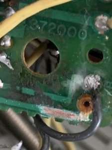
Ok, I scratched back a layer of metal to solder to. I’m going to hold off on soldering this end until I complete the other jumps. I watch a video of someone applying some glue after the solder to the trace to add strength. Is this advisable? Is epoxy ok for this?
92296019-61AE-4BEA-9858-649CAB7E0838.jpeg
 
Last edited:

Jboulukos

Member (SA)
May 25, 2020
166
20
18
Cali, Colombia
Looking good.
Remember to follow the tracts and determine what is on one side and the other.
For that capacitor take care as above you need to extend the leg to reach to the other side of the crack.
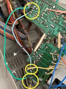
Ok for wire 3 with the capacitor within the crack...I’ve read through our notes and discussion. Can you tell me how to extend the capacitor leg? And elaborate.
I am to solder an extension onto the Capacitor leg in order for the leg to have a taller area to solder a jump wire to it? If so, do I just use some stripped wire? This is a small jump from 345 to 352 on the same side of the crack, correct? The jump soldered to 345 will be the same location as the 4th wire connection point? Why am I I extending the leg that in the crack If we aren’t soldering to it? Just need some specifics here so I can solder it all correctly. Much appreciated as always.

A7E4F071-1742-4EA2-A8E6-2C01F9695F49.png
 
Last edited: