M9998 quiet channel on deck in stereo/wide

docs

Member (SA)
Jun 26, 2010
2,558
381
83
52
United Kingdom
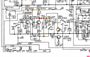
The only discrepancy I found was at Q813 collector which for weak channel has 0.10v but it should read 4v.
I've been checking components to try and find why, including replacing Q813 (C1570) but all other components read ok with one exception.
R894 when tested against R994 reads low resistance, it should be 1m. R994 does read 1m in board while R894 reads 0.45 ohms. I lifted a leg of the resistor and it reads 1m so assumed good. I didn't need to lift a leg to rad the resistance of R994 though. This was read with Q813 out of board and in board with the same result.
Any suggestions appreciated.

m9998 left chan quiet.png
 

docs

Member (SA)
Jun 26, 2010
2,558
381
83
52
United Kingdom
Thanks Norm, will give it a try while Q813 is removed and desolder/clean/touch up some of the solder points.

Edit:
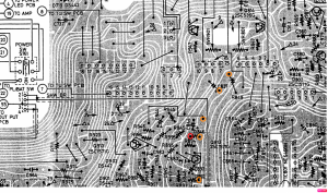
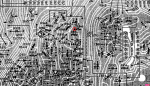
Desoldering leg highlighted red gets the 1M resistance restored but as soon as I resolder it back in, it reduces the 1M back to 0.40 ohms.
R846 tests at 4.7k, do I need to follow the opposite leg traces and resolder/clean highlighted orange etc?

m9998 left chan 2.png
 

Attachments

Last edited:

docs

Member (SA)
Jun 26, 2010
2,558
381
83
52
United Kingdom
What a curious issue. Will get back to it this weekend but failing replacing that 1M capacitor, not sure what else to check but to continue to resolder/replace a few things.
 

hopey

Member (SA)
Dec 28, 2014
1,287
287
83
Melb AU
I've been watching this one I have a similar problem on a Toshiba, could it be a failed resistor? Its in the Tape preamp before the volume trim pot.
 

Superduper

Member (SA)
Take a look at R894 on the schematic, and think about what it would take to make a circuitous path back towards the two leads of that resistor. There is NO direct low current path unless Q813 is shorted base/collector. There are other paths but it becomes even less likely because multiple components will have to be shorted. And if you say that R894 is shorted in circuit with Q813 removed, it simply MUST be a short in the PCB, and that would most likely be caused by bridged solder pads or by the the traces on the PCB shorting. Also, note that glue has been known to breakdown and go conductive over time, so you'll want to check that too.

IF R846 is testing 47k, and it tests this way (in-circuit), then the opposite leg has nothing to do with your short. That's because any parallel circuit would have to go through that 47k resistor, and there's no way to get to 0.45Ω through that path.

BTW, with R846 out of circuit, does solder pad (R846 + R849) get 4v?

If you want to verify if the short is in the PCB, just remove the r894 and test those 2 pads. If you are getting low resistance, then the short persists, remove Q813 and retest. If you are still getting low resistance, then continue removing components and clean pads and traces until you find the source of the short.

Note that I'm making presumptions based on ordinary circumstances. If the PCB has been modified, circuit modified, etc. all bets are off the table.
 
Last edited:
  • Like
Reactions: baddboybill

docs

Member (SA)
Jun 26, 2010
2,558
381
83
52
United Kingdom
What a head ache, still no nearer. Traces look ok, continuity is ok, checked component side to try see any glue or obvious issues. I think replacing parts has made it worse, had low volume in chan, now none. Maybe the transistor I bought to replace original was knackered.
 

floyd

Member (SA)
Jan 9, 2022
1,059
788
113
55
Maryland usa
What a head ache, still no nearer. Traces look ok, continuity is ok, checked component side to try see any glue or obvious issues. I think replacing parts has made it worse, had low volume in chan, now none. Maybe the transistor I bought to replace original was knackered.
Dave this might sound stupid but have you checked the actual heads on the tape deck ?.
 

docs

Member (SA)
Jun 26, 2010
2,558
381
83
52
United Kingdom
Lol Norm, as thankful as I always am and super courteous, simmer yourself a little, there is just no need.

The original transistor in the board was a 1570, c1570G9F to be exact. I replaced it with this. But as you suggested, it didn't resolve anything so I will revert back to the original.
I replaced the resistors and 1 cap associated with the traces where the low ohm readings were read across the transistor pads, simply in the thinking that there could be a short caused by these components. I did this after testing continuity between pads, results were as they should be, good on connected traces, non continuous on unconnected pads and traces.

I am going to revert to original as things seem to be going nowhere to my limited mind and will try again. The cables which connect between boards dont help and will probably start deteriorating eventually so once removed for replacement back to original, I need to be careful to not continue the process too many times to cause another issue.

For the expert, this would be a 5 minute job i'm sure, but for me, someone who has learnt from you and this site and successfully repaired 100's of other people's units, for free, well I do it because a) i'm somewhat capable and intelligent enough to try and b) for the love of the hobby. I don't do it because I know how to. Bare that in mind.
 

hopey

Member (SA)
Dec 28, 2014
1,287
287
83
Melb AU
Any chance it could be the Dolby chip? I know you can by pass but it may still run through the IC?
Should be able to confirm by swapping left to right?
 
Last edited:

H3NK3L

Member (SA)
Dec 17, 2020
159
121
43
France
Same issue here, no matter what the source (radio / phono / tape)....opened it up an thouroughly desoldered and cleaned the "mode" switch... odd thing happening....now stereo and wide work (sound on both channels, equal strength) for phono and radio...but not for tape.
Dolby : led doesnt light up (may be faulty or a circuit board problem, had tha ton the power led, by bridging it directly to theincoming leads it works fine) :
- dolby works (soundwise at least I hear a difference, dolby switch clean and operational
- tape : still only getting right channel on stereo and wide (mono works fine) / tapehead is ok
- R894 and R994 are fine (1.002 M and 1.003 M)

but sideissue but perhaps related :
- left VU meter does not work (no matter what the source)
- left VU meter does indicate battery level (no batteries in : 100 pct, permanently)
- right vu meter works with phono - left does not
- REC does not work at all, no erasing no recording
- the input level dials L and R work...but..permanently seem to be concidering the inbuilt mics as input (only reproduces them doesnt record them)
- input level dial set to max gives a hshshshshs noise no matter what source I m playing (and it does it equally on both L and R channel)
- when hitting REC and PLAY, phono/radio : neither VU meter works no matter what the dolby/alc setting (tape does roll well)

Things I ve done....
- repaired the battery check/dial light button (it was permanently on) : works fine now
- took the 14V in on the battery/dial light button to an external button and then to leds to light them permanently ,
- 0 and 14V now come from dial/light button (OUT) or via external button from dial light button (IN)
Maybe a wrong thing to do but as i figure it : the power to the dial lights either come from where the goes into the original button (via a new permanent on/ permanent off button, thus "bridging" the original button - or from the original button (when the external new button is OFF). When pressing both I dont really see what can go wrong...but again maybe i m wrong). My 4 leds are as follows : 2 paralled for VU meters - in series with the 2 paralelled for tuner dial. They re intended for 6 to 12 volts, this way I gather each pair gets half the 14V. Works like a charm.

Basically : besides this Sanyo being all but accessible.... tape is my only problem, and for a while now I havent been able to figure out what the problem can be... (tried ; Record bar - source button (that helped for the other inputs (Radio and phono),....) - thought there was a Dolby/ALC problem but that switch seem to work (to the ear, the indicator led does not work.). And the left VU meter seems to be for "battery level" only (and battery is always 100, except when i actually put batteries in..then it seems accurate)

This is the most nightmarish boombox I ve ever dealth with between the spaghetti wiring, the numerous sockets,....Just wouldnt like to turn it into a bluetooth radio thing.

thourouglhy cleaned all switches and the rec bar - checked for any further "loose" of broken channels on the pcb, didnt find any