M90 tape apparently dea
- Thread starter Yatsuya
- Start date
- Status
- Not open for further replies.
I am coming back right now from the cellar. The zener is ok. I tried as well to test the live voltages of Q712 with following results:
B 12.65V
C 0V
E 1.8V
Unfortunately, I fried FR703 again, but I have a couple more of these
B 12.65V
C 0V
E 1.8V
Unfortunately, I fried FR703 again, but I have a couple more of these
Yatsuya. I don't know how you can get those readings unless you blew FR703 in the middle of testing and after taking the B readings. The base, at 12.65 v does seem to indicate that the zener diode is working OK. And the E at 1.8 volts clearly indicates to me that this transistor is toasted. But the collector should not read zero because that is the source voltage. Therefore, you probably tested the base, and emitter properly, then inadvertently grounded the probe while testing frying FR703 again before testing the C voltage.
In any event, replace that transistor and voltage should be restored back to normal on the regulated rail of E after also replacing FR703.
In any event, replace that transistor and voltage should be restored back to normal on the regulated rail of E after also replacing FR703.
After another round of rework (replaced Q712, FR702 and D720), I have now following voltage readings:
B 12.84V
E 12.4V
Unfortunately, the motors still do not spin. Should I try checking other transistors as well?
B 12.84V
E 12.4V
Unfortunately, the motors still do not spin. Should I try checking other transistors as well?
Well, that is good news. It means you are making progress. At this point, you should be able to read 12 volts +/- at the motor against ground. (+ to motor, - to ground). If you are not getting power at the motor, then check for continuity breaks in the wiring or circuitry.
Check for 12 volts at motor
YES...............................................................NO
Check Q710, then Q709....................... Check for continuity of wiring/circuitry from regulator to motor.
This only pertains to the capstan motor. The reel motors work independantly of the capstan motor and is powered/controlled through IC702. IC702 in turn receives power via regulator Q701 and protected via FR701.
The motor receives positive power from the regulator. It is grounded through Q710, which is switched on by Q709. Q709 gets it's start signal from the controller IC. You DO realize that if the controller IC's are bad, that you have a large brick, right?
All tape functions get their go signals via IC701. If that IC is toast, then that is very very bad news because it can't be bought anywhere, if I'm not mistaken.
At this point, to prevent spending too much time/money on this deck, it might be prudent for you to do a comprehensive voltage check of test points by comparing readings against the service manual to see what you are up against, and how much damage there is. It's important to know whether it is common components that have failed, or if there is issues with the unobtainable components.
It's too bad that we don't know the original code to burn a PIC. :'-(Superduper said:All tape functions get their go signals via IC701. If that IC is toast, then that is very very bad news because it can't be bought anywhere, if I'm not mistaken.

Superduper, first of all let me thank you for sharing your knowledge.
I realize that I have to perform a thorough check of the remaining transistor voltages on the path to the capstan motor. I do really hope that I will find the cause of the problem soon.
I realize that I have to perform a thorough check of the remaining transistor voltages on the path to the capstan motor. I do really hope that I will find the cause of the problem soon.
If you have power at the motor, then grounding the other tab should power it up. Normally, that leg is sinked through Q710. It could be bad. But if it's good, then it gets it's signal to turn on via Q709. Q709 in turn gets it's signal throught the IC. The reason why the IC doesn't power up IC710 directly is because IC's typically can only handle very little current. If Q710 requires more power than the IC can handle, then that duty is passed off to a small pre-driver transistor (Q709) first.
Sorry for not posting updates more frequently, but I will have to wait for the weekend, before doing further tests on my M90
how are ya getting on with the M90 !!! this is like a real story can't wait for the out come!!! good luck
In the last couple of weeks I have started working on my M90 again. After having checked and repaired the voltage regulator, I have focused on the capstan motor drivers (Q709/Q710) and I have done a complete recheck of this part of the circuit, following Superduper's original advice.
This time I was able to find out that Q710 is blown. So, I have searched for a replacement, which in my case is a BC 635. I have soldered in the new transistor and now I am very glad to tell you that the tape is working again!!! All logic controls are fully functional and the AMS is working as well. I have noticed that the tape speed is lower than it should be, but I understand that it can be adjusted by turning a variable resistor attached to the reel motor.
The M90 sounds beautifully!!! When I found it abandoned, I could not imagine what an adventure I would have been put into. I could learn a lot during this time and I want to thank all forum members, who have given me a word of encouragement.
Superduper, I thank you for sharing your deep knowledge with me. Without your explanations I would never been able to revive this beautiful piece of technology. And now, let's find another one")
This time I was able to find out that Q710 is blown. So, I have searched for a replacement, which in my case is a BC 635. I have soldered in the new transistor and now I am very glad to tell you that the tape is working again!!! All logic controls are fully functional and the AMS is working as well. I have noticed that the tape speed is lower than it should be, but I understand that it can be adjusted by turning a variable resistor attached to the reel motor.
The M90 sounds beautifully!!! When I found it abandoned, I could not imagine what an adventure I would have been put into. I could learn a lot during this time and I want to thank all forum members, who have given me a word of encouragement.
Superduper, I thank you for sharing your deep knowledge with me. Without your explanations I would never been able to revive this beautiful piece of technology. And now, let's find another one
monchito said:


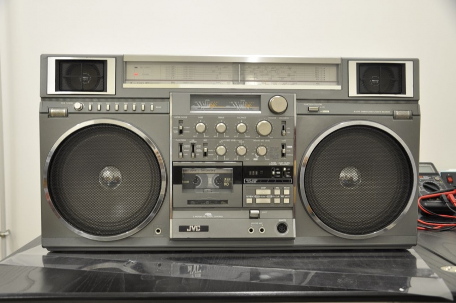
 this thread needs to see a pic of that bad boy!! Welcome to the M90 club!!

- Status
- Not open for further replies.