JVC M90 FM reception issue

Dancorp

Member (SA)
Apr 13, 2017
127
10
18
Marseille, France
Hello guys,

Finding an M90 for 200 bucks is nice, but of course nothing works perfectly :)

If I switch on the boombox on FM, I have a little bit of reception, but that disappears slowly.
I have some noise, and therefore some signal, but not on the whole FM band. Half of the FM band is indeed silent.
Any "back and forth" on another band makes me lose reception on FM.
Touching a capacitor or any other ground point generates noise.

The first long job was to disassemble the switch strip and clean them one by one.

1658609453498.png

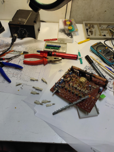
I did some measurements on the ICs and transistors.
Everything seems OK on transistors


But it's the ICs measurements that are the most interesting:
If everything is globally OK on the IC1 voltages, (except pin 15)), I noticed a surprising phenomenon: when I measure pin 8 of IC1, the reception is very partially restored, at low volume and mixed quality. This is followed by a slight increase in volume and then a slow decay to nothing.
At the end of less than 2 minutes, we return to silence until the next tickling of pin 8.

At the output of IC1, i.e. on pin 9, we keep a stable voltage around 2.4v. (This also corresponds to TP2)

However, just after C91, we attack the MPX on its pin 2 and there it is the disaster.
The VCC of the chip is stable but pins 2, 4, 5, 6,, 13, 14, 15 never have their nominal voltage and this one varies according to the low volume of sound in reception, the one consecutive to the miraculous measurement of pin 8 of the IC1.
The voltages therefore decrease irremediably, at the same time as the reception.


Thanks in advance for your help

Dan
 

floyd

Member (SA)
Jan 9, 2022
1,059
788
113
55
Maryland usa
Since you've already cleaned all the switches we can eliminate that problem I do have problems to this day with them band selector switches but I've never rebuilt them not only that it's the function selector switch when those get dirty you have to mess with it to get anything to work right. Old analog tuners are power hungry devices and if there's any lag in the power supply you may not get any reception just like when the batteries go dead the reception gets worse.
 

Tinman

Member (SA)
Mar 4, 2019
518
264
63
USA
Since you've already cleaned all the switches we can eliminate that problem I do have problems to this day with them band selector switches but I've never rebuilt them not only that it's the function selector switch when those get dirty you have to mess with it to get anything to work right. Old analog tuners are power hungry devices and if there's any lag in the power supply you may not get any reception just like when the batteries go dead the reception gets worse.
Funny, I'm having a power problem on an SCR-8 and it's exactly like you said.
FM works on ac but not with batteries (batteries are good).
On ac I can tell the volume just isn't there and the LED indicators are dim.
I assume the batteries aren't putting out enough to overcome whatever the problem is, hopefully it's just a resistor.
I have to start tracing and testing.

OP, awesome job taking all of those switches apart.
I took my M90's FM switch apart to clean it.
I had to cut the sliding piece that unlocks the previous button then splice in a new piece, huge pita.
It'd be great if something easy like a recap of the board solved it.
 

floyd

Member (SA)
Jan 9, 2022
1,059
788
113
55
Maryland usa
If I remember correctly there's an internal external antenna switch that might be a good place to look too.
 

Dancorp

Member (SA)
Apr 13, 2017
127
10
18
Marseille, France
Since you've already cleaned all the switches we can eliminate that problem I do have problems to this day with them band selector switches but I've never rebuilt them not only that it's the function selector switch when those get dirty you have to mess with it to get anything to work right. Old analog tuners are power hungry devices and if there's any lag in the power supply you may not get any reception just like when the batteries go dead the reception gets worse.
I'll end up disassembling all the switches !
Thanks for the advice, I'll keep you informed
 

Tinman

Member (SA)
Mar 4, 2019
518
264
63
USA
Well, I found the culprit on mine, I believe it's FR164.
It's a 1/8 watt, 4.7 ohm fr resistor.
So small but caused such a big headache.
This SCR-8 is back up to full power and sounding great.

Anyway, Dancorp, keep tracing and testing and you'll find your problem too.

PXL_20220724_003351254.jpg
 
  • Like
Reactions: Huffers

Dancorp

Member (SA)
Apr 13, 2017
127
10
18
Marseille, France
And there you have it.
Cleaning the switch was beneficial!
Thanks again for your advice.
Let's move on to the next question now lol

EDIT: Arrrgggg... It still going wrong
I have to work on caps....
 
Last edited:

floyd

Member (SA)
Jan 9, 2022
1,059
788
113
55
Maryland usa
And there you have it.
Cleaning the switch was beneficial!
Thanks again for your advice.
Let's move on to the next question now lol

EDIT: Arrrgggg... It still going wrong
I have to work on caps....
Sometimes these caps are plain dried out there's no bulging on the top the only way to test continuity is to test the legs of the cap at the PC board compared to the specs on what it should be. I had many car amplifiers that looked fine but just didn't work after recapping they worked perfectly.
 

Dancorp

Member (SA)
Apr 13, 2017
127
10
18
Marseille, France
I finally managed to fix part of the problem after replacing the AN7410N chip.
The reception is now stable, and I can switch to the other bands without any problem.

The last problem seems to be the FM alignment.
Indeed, it is necessary to set the tuner on 105MHz to receive a station transmitted on 89Mhz.

Is there a simple method to manage this problem?
(I can't interpret page 9 of the service manual)
 

Superduper

Member (SA)
Unless you have a SSG (stereo signal generator), you are not going to be able to adequately align the tracking. The instructions are asking you to set the tuner dial to one extreme (low) and then inject an 87.5mhz signal, 400hz modulated to 22.5khz deviation. Then adj the indicated set points until you hear the modulated tone clearly through the speakers. Then do the same at the other extreme. After that, then do the same for 90mhz and 106mhz, repeat over again until no improvements. No, there is no "simple" way to do this.

The generator outputs a precise RF signal, modulated so you can hear audio (tone) at that frequency. In other words, if the tuner dial is set to 87.5, the generator should be set to output that same frequency. You'll make the necessary adjustments until you can hear that tone clearly which indicates that your tuner is now able to tune 87.5mhz. Unfortunately, the adjustments will affect other channels so that's why you then adjust at the other extreme and keep doing it. Ideally, once the tracking is properly aligned, any frequency on the dial should be able to be received and you can verify this by setting the generator to output a signal at that frequency, and the tuner should be able to tune there and you should hear the modulated signal through the speakers.

Stereo Signal generators are not cheap, you can do an eBay search to see what is out there. Sencore makes a couple of AM/FM Stereo Analyzers that will probably suffice for anything you will be doing with your boombox tuners. The SG165 is fairly plentiful but you won't be able to adjust deviation which probably isn't critical and you'd still be able to use it to align your tuner. However, many are broken now and most are sold as-is with missing leads so buy carefully. The SG80 is a far more advanced and better instrument but rarely available and costs much more. If you can afford it, something like the Panasonic VP-8132 is ideal, but they cost a fortune and are lab grade instruments, probably overkill for a diy hobbyist. There are some made in china toy-like generators, I can't say whether they will or will not work. In this case, it might be "good enough" to do tracking adjustments, but probably not much more.
 
  • Like
Reactions: Funkateer38