Greetings, dear members of the forum! My name is Vadim. I have been studying your forum for a long time and found here a lot of useful information for myself, which is nowhere else, this is truly a very valuable knowledge these days, when almost no one wants to take on the repair of old tape recorders. Last year I got a rather battered M90, which has many problems: the cassette deck does not work, the radio does not work, the potentiometers do not work. I decided to start with the hardest part - the cassette deck. Disassembled the box, I found that the cassette deck board has a crack along its entire length, I repaired this crack and repaired all damaged contacts. I also replaced the FR704 fusible resistor, which is responsible for the operation of the solenoid. I also installed new straps. I decided to test the deck for operability and found that when the tape recorder was turned on, the solenoid core retracted and remained in this position until the power was turned off. This causes the fusible resistor to get very hot. My guess is that this solenoid should only work momentarily. When the power was turned on, the main deck motor did not spin at all, although it should. I checked the motor and it turned out to be dead. After installing another working motor, nothing has changed. Then I replaced the control motor driver and the main motor started working. But the deck is still unfair. When I turn on the power, the solenoid works and remains pulled in all the time, the main motor also turns and the cassette deck raises and lowers the part with the magnetic heads all the time in a circle. I realized that the electronics does not see the position of the control gear. When checking the photo of the sensor, I realized that it does not work. After looking at how this sensor should work on another deck from the M90, I saw that one of the LEDs should be on, which does not happen. I replaced the photo sensor with a working one - but it did not work, it still does not work and does not light up. In the diagram, I saw that this photo sensor is connected to the IS701 control processor, but I have no idea how to check this processor. For almost a week I have been trying to figure out what the matter is, but all to no avail ((Perhaps someone had a similar problem and can suggest something? Thanks in advance to everyone! Respectfully, Vadim.
JVC M90 didn't work cassette deck (photo coupler problem?)
- Thread starter brovKO
- Start date
It may need a new main gear.....i had this problem twice where the heads just rotated in a cycle....member Docs fixed it for me maybe he can help....he and superduper know the most about the m90 oh and caution.....good luck Sir
Last edited:

Thank! The main gear looks great, but the photo sensor does not work (Because of which the heads repeat the program cycle all the time without stoppingIt may need a new main gear.....i had this problem twice where the heads just rotated in a cycle....member Docs fixed it for me maybe he can help....he and superduper know the most about the m90 oh and caution.....good luck Sir
Hi! Yes the solenoid should run for less than one second, or else FR704 begins to fry, so your batteries don't overheat. Usually a broken belt prevents the solenoid from turning off because the drive gear can't turn, which is critical to getting a signal to the photosensor to tell the control chip to turn off the solenoid.
But if your belt is fine and the drive gear is turning, AND you've ensured that the photo LED is OK (it glows red) then you could have a bad photo sensor X751, or the reflective sticker on the drive gear is not good enough anymore. Mine had some water damage, so I replaced it with a mirror-chrome plastic sticker, and it allowed the sensor to pick up the reflections properly as it turns.
If you notice the pattern on the wheel, it (roughly) matches the "I.TM" signal along the upper part of the timing chart - this signal is the pin that goes from the photo sensor into the control chip (green line). As the drive gear turns, D751's light is reflected onto the X751 photo sensor, in different time periods of on and off.
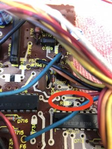
It's actually an inverted signal - when the O.LAMP signal turns on the photo LED, and the sensor picks up its light, the sensor opens up a connection to ground (the purple line) and pulls I.TM low. Normally, I.TM is held high by the the resisor by the blue arrow, R724.


But if your belt is fine and the drive gear is turning, AND you've ensured that the photo LED is OK (it glows red) then you could have a bad photo sensor X751, or the reflective sticker on the drive gear is not good enough anymore. Mine had some water damage, so I replaced it with a mirror-chrome plastic sticker, and it allowed the sensor to pick up the reflections properly as it turns.
If you notice the pattern on the wheel, it (roughly) matches the "I.TM" signal along the upper part of the timing chart - this signal is the pin that goes from the photo sensor into the control chip (green line). As the drive gear turns, D751's light is reflected onto the X751 photo sensor, in different time periods of on and off.
It's actually an inverted signal - when the O.LAMP signal turns on the photo LED, and the sensor picks up its light, the sensor opens up a connection to ground (the purple line) and pulls I.TM low. Normally, I.TM is held high by the the resisor by the blue arrow, R724.
By the way, the "I" in I.TM means it's an input, and O.LAMP is an output.
Since O.LAMP has no bar over it, it's not an inverted logic signal like I.TM is.
The H and L inside of circles, next to each pin, refer to a note near the timing chart that I didn't clip, that mentions the fact that a logic "high" signal is anything over 2V, and a logic "low" signal is anything under 0.8V.
You can see on the timing chart how the control chip enables O.LAMP right before the cycle and turns it off right after.
When it's enabled, it actually has to go through an inverter (IC704 pins 3 and 4) so that the active signal is low; this is done so that D751 can tie to main power (pink line, through R711), instead of relying on the control chip to provide its power. Easier for the chip to pull something to ground.
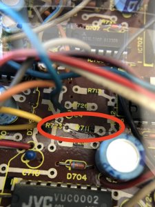
By the way, were any top-side elements damaged from the board's crack? There are printed traces, and printed resistors on there.

Since O.LAMP has no bar over it, it's not an inverted logic signal like I.TM is.
The H and L inside of circles, next to each pin, refer to a note near the timing chart that I didn't clip, that mentions the fact that a logic "high" signal is anything over 2V, and a logic "low" signal is anything under 0.8V.
You can see on the timing chart how the control chip enables O.LAMP right before the cycle and turns it off right after.
When it's enabled, it actually has to go through an inverter (IC704 pins 3 and 4) so that the active signal is low; this is done so that D751 can tie to main power (pink line, through R711), instead of relying on the control chip to provide its power. Easier for the chip to pull something to ground.
By the way, were any top-side elements damaged from the board's crack? There are printed traces, and printed resistors on there.
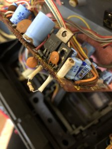
I'm ashamed to admit, but I could not even think that these marks are traces and resistors. I looked closely at the reverse side of the board and saw that several contacts were still broken, the resistors R711, R722, R720 were also damaged. I'm not sure if these resistors are affecting the work of the photosensor, I restored the connections with conductive glue - but nothing has changed. The photosensor LED is still off. I don't have a service manual, tell me how can I replace the resistors R711, R722, R720? Thank!There are printed traces, and printed resistors on there.
Attachments
-
 149.1 KB Views: 58
 -
 167.9 KB Views: 62
 -
 164.3 KB Views: 61
 -
 182.5 KB Views: 59
Click on "Library" at the top of the site, and go into the JVC folder. The M90 manuals are in there.
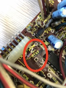
I'm almost certain that if you fix R722 (330 ohms), you'll fix the solenoid issue.
Just use a normal resistor to replace the damaged ones, and use jumper wire to reconnect the cracked traces.
R720 (47K) and R722 (100) are involved with the circuit that prevents you from accidentally recording over a cassette with record tabs broken off to protect the recording, so that issue wouldn't have been as obvious until later.
Hey! I did everything as you described - but nothing changed ((In addition, the engine stopped rotating again and the solenoid does not work. I changed the fuses again, but it didn’t work (In addition, the cassette deck on my second M90 also stopped working (( (Click on "Library" at the top of the site, and go into the JVC folder. The M90 manuals are in there.
I'm almost certain that if you fix R722 (330 ohms), you'll fix the solenoid issue.
Just use a normal resistor to replace the damaged ones, and use jumper wire to reconnect the cracked traces.
R720 (47K) and R722 (100) are involved with the circuit that prevents you from accidentally recording over a cassette with record tabs broken off to protect the recording, so that issue wouldn't have been as obvious until later.
Can you make these two cassette deck boards for me? I can send you a turn of DHL my decks boards. I'm willing to pay well for your work. Thank!
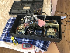
Sorry to hear it's still not working, unfortunately I am not in a position to help. The best method is your setup, with the entire box open so you can power up the deck as you try repairs on it, to test it fixed it. Are you sure you repaired every connection from the crack? Every silver line on the top side around the crack got a jumper wire, right? Maybe go back and check all of those with a meter.
Also, the holes that go through the board are plated, so if any of those are cracked, there could also be missing connections elsewhere. You might want to go through the board and check any questionable areas for continuity.
Also, the holes that go through the board are plated, so if any of those are cracked, there could also be missing connections elsewhere. You might want to go through the board and check any questionable areas for continuity.
I did just that, disassembled the radio and removed the cassette deck (disassembled, cleaned and lubricated the mechanical unit, installed new straps). Initially, I made the solenoid and the main motor work. To check what the problem was, I rearranged the transistors from the working deck of the M90, in the end it all came to the fact that I have 2 non-working decks (cry)continuity
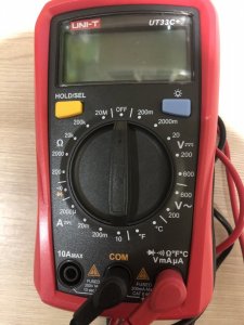
It seems as if the solenoid and main motor on both decks are not powered. Where to start first? Can I properly diagnose all components with a digital multimeter that I have? I am very bad at circuits and all radio components, but if I was guided, I think I could do it. At the moment, I don't even know where to start again. I replaced all the fusible resistors but the solenoid and motor do not work (checking the solenoid and motor showed that they are working).
Attachments
-
 138.2 KB Views: 56
If you aren't getting any power to the motor, check FR703 and FR704, those are the fusible resistors for unswitched power, which the motor and solenoid use.
sorry for my late reply on this
rotate the main gear without power.....if it just goes round and round without locking into place it is 100% broken, if it locks into place it's fine
if the gear is broken don't panic, you can use the gear out of an m60 m80
rotate the main gear without power.....if it just goes round and round without locking into place it is 100% broken, if it locks into place it's fine
if the gear is broken don't panic, you can use the gear out of an m60 m80
Last edited:
As suggested above, if you haven't downloaded a service manual already, start with that.
I'd also suggest getting your good deck working then take voltage readings of the working ICs and compare those to the ICs on the bad board.
Draw pictures of each IC and note the voltages at each leg.
Once you determine where the problems are, you can narrow down which tracings and/or componets might be bad.
Follow the tracings on the non component side of the pcb and test for continuity between point A and B.
You can use the good board to test and verify everything against the bad board.
Also, make sure you verify that the conductive glue you used is actually working otherwise you'll have to make jumpers.
I'd be leery of the glue cracking.
If your board cracked in 1/2 and it has numerous printed traces and resistors, then you really shouldn't be fixing it from the top side. There is no way to do that reliably because (1) the printing is compromised and (2) the components that the crack runs through are destroyed and can't be repaired since there's no way to replicate the original value by bridging it with conductive adhesive. Furthermore, most 1-part conductive glues/epoxies these days require a heat cure meaning you need to bake the repair for about 10 - 30 minutes, time depends on heat. Until the repair is cured, it will not conduct, or conduct sufficiently. From your photos, there are an enormous number of broken connections.
What you should do is rely on the PCB wiring diagram while consulting the schematic to recreate the circuitry from below. The reason is you simply can't solder to printed traces... they aren't solderable. So what you'll be doing is soldering from beneath directly to component leads or solder pads. But what about the printed resistors you say? Well, no matter that they are printed on the top side, printed traces always eventually flip to and connect with the bottom side by means of "vias" (think of them as connections that bridge the top trace with a botton trace and they generally look like small black dots. Sometimes, they connect to a landing or solder pad. I'm not going to explain the entire process here but I did a repair a very long time ago that I documented very well on a repair that had lots of broken connections due to degraded printed traces and resistors. Take the time and read the whole thread, it's very long but will provide you invaluable advice on how to repair. The important thing to remember is that if a printed component or trace is suspect, cut them out of circuit on the top side, and on the bottom side, replace the connection or component. If you don't trim off the connection on the top side to isolate it, especially with respect to the resistors, they might result in a parallel circuit that will alter the resistance value of any replacements you tack on from beneath.

 boomboxery.com
What you should do is rely on the PCB wiring diagram while consulting the schematic to recreate the circuitry from below. The reason is you simply can't solder to printed traces... they aren't solderable. So what you'll be doing is soldering from beneath directly to component leads or solder pads. But what about the printed resistors you say? Well, no matter that they are printed on the top side, printed traces always eventually flip to and connect with the bottom side by means of "vias" (think of them as connections that bridge the top trace with a botton trace and they generally look like small black dots. Sometimes, they connect to a landing or solder pad. I'm not going to explain the entire process here but I did a repair a very long time ago that I documented very well on a repair that had lots of broken connections due to degraded printed traces and resistors. Take the time and read the whole thread, it's very long but will provide you invaluable advice on how to repair. The important thing to remember is that if a printed component or trace is suspect, cut them out of circuit on the top side, and on the bottom side, replace the connection or component. If you don't trim off the connection on the top side to isolate it, especially with respect to the resistors, they might result in a parallel circuit that will alter the resistance value of any replacements you tack on from beneath.
The Saga Continues (blu_fuz 5350)
Ok, I'm starting a new thread since the old one just got too long, and as this thread only will include the fixes without the 200 encouragement posts, it might be more helpful for folks needing to fix a similar type of issue. This regards the tuner to Joe's (Blu_Fuz) RX-5350 repair thread...
boomboxery.com
Hello! Thank you all so much for your help!) I follow the topic and see all the messages as soon as they appear) I decided to take a short break because these boxes will drive me crazy) I plan to start my M90 again on Tuesday. With your help, I am simply obliged to complete the matter to the end)
Hello! After a short break, I decided to go back to rebuilding my decks. I decided to start with the one that was originally working (without cracks).If you aren't getting any power to the motor, check FR703 and FR704, those are the fusible resistors for unswitched power, which the motor and solenoid use.
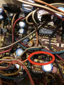
On your advice, I replaced the resistors FR703 and FR704 and the solenoid is now working again. But the motor is still worth it. I noticed that the Q 702 transistor heats up while the deck is connected to power. This is normal? What are my next steps to resume the operation of the capstan motor? I also unsoldered one of the solenoid contacts so as not to burn the replaced resistor while the motor is not running.
Thank you very much to all the forum participants, you are helping me unreal)
Attachments
-
 203.4 KB Views: 65
 -
 124.3 KB Views: 64
I have studied a lot of information regarding radio parts and how they work. I also did a lot of checks with a multimeter. Now I know that the driver of the Q710 motor requires replacement (which is the best alternative for replace it?) and it does not receive power at all to any contact, despite the fact that 7 volts from the emitter come out from the Q701. The Q709 motor driver also does not receive power to any contact. I also found that only 18 volts are supplied to the Q702 to the central contact (I assume that this is a collector), there are no signals from the other contacts. What do you recommend to check next?
By the way, about 18 volts is also supplied to the Q701, is that not a lot?
By the way, about 18 volts is also supplied to the Q701, is that not a lot?
Today I re-checked and saw that the Q712 receives 19.8 volts to the collector and also 19.8 to the base, but at the emitter 0. I assumed that the Q712 was closed. I dropped out Q712 it and took measurements without it and nothing has changed, 19.8 volts are supplied to the base, but despite this, there is no short circuit between the base and the collector. How is this possible?
I suppose that the Q712 is already dead. Could there be an alternative BD139 instead Q712?
I suppose that the Q712 is already dead. Could there be an alternative BD139 instead Q712?
I see so many cracked wires and resistors in your images.
All of the testing you are trying to do with the components is pointless if the PCB still has problems.
All of the testing you are trying to do with the components is pointless if the PCB still has problems.