¡Bienvenido a bordo! Es posible. ¿Qué has tratado de reparar?fededesalta said:Soy nuevo en el foro y tengo el mismo modelo de Hitachi, se pudo arreglar?.Tengo el mismo problema.Gracias.
Hitachi TRK 8190 - no stereo reception in FM
- Thread starter beamrider
- Start date
-
- Tags
- hitachi 8190
Fm no sintoniza claro ni se enciende la luz de fm estereo
Tambien tene los controles de graves y agudos con troblemas.
Tambien tene los controles de graves y agudos con troblemas.
Los controles de bajos y agudos probablemente podrÃan repararse con una limpieza a fondo. Sugiero descargar el manual de servicio para la luz de FM estéreo.fededesalta said:Fm no sintoniza claro ni se enciende la luz de fm estereo
Tambien tene los controles de graves y agudos con troblemas.

http://www.mediafire.com/file/thsbh6i4lglf1es/Hitachi_TRK-8190E_Service_Manual.pdf/file
Gracias por la respuesta. Ya solucione lo de el potenciometro.Desarme uno que no uso y le adapte los contactos de adentro. quedo muy bien.Con Fm me paso que cuando lo compre estaba muy muy sucio, decido pasarle aire a precion y despues ya no sintonizaba en estereo. La primera vez que le pruebo la sintomia de fm si recibia en estereo. Alguna idea que me puede haber pasado?


Hola , pudiste reparar la recepcion de fm estereo?beamrider said:He limpiado el interruptor de banda y el interruptor selector de funciones, pero no ha hecho ninguna diferencia.
La resistencia a través de RT301 fue ~ 1200 ohmios. PodrÃa ajustarlo a 1097, pero la luz estéreo nunca se encendió, asà que la he revertido por ahora.
+ el interruptor estéreo / mono funciona para la cinta, por lo que no puede ser el interruptor en sÃ.
Great suggestion for an expert here...... but can you make things simple by directing what to do...toshik said:Was the pilot tone frequency measured?
Please help with things to look at and follow up.
Otherwise the comments you make are of no help here....
No offence though... just a suggestion!
I tried to follow these steps from the service manual using my soundcard scope). But I couldn't obtain a 19khz signal anywere, although the instructions aren't that clear. I got either 50hz or 100hz depending on how I made the connections.. Some further help would be appreceated.
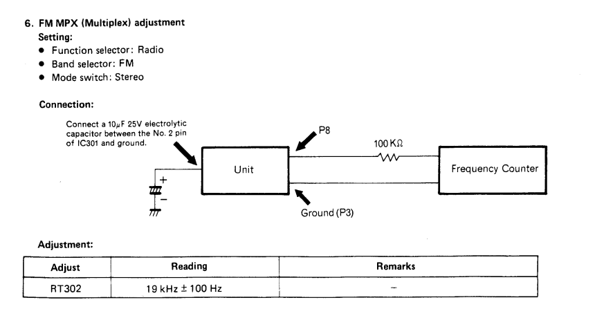
Ok, first, you need to eliminate either RT301 or RT302 as possible problem sources. RT301 is a 1k Ω variable resistor and RT302 is a 4.7k Ω variable resistor. Both should be adjustable from 0 to the max reading. You might not be able to get max resistance if there is a parallel path, but something is wrong if you can't get as low as zero. If the readings aren't within specs or not what you are expecting, take them out of circuit and check again. No sense proceeding if either of these are failed or out of spec. On post #19, you mentioned something about getting a high resistance reading from RT301. Although that's not the adjustment for pilot signal, the readings that you are sharing does not sound right for a properly working 1k Ω pot.
Then once you've confirmed this, if any pot is/are bad, replace and recheck. If problem still persists, you should consider that it's entirely possible that your MPX decoder chip is bad. Happens a lot.
As for your 19khz adjustment, you should understand that a "true" frequency counter is the best tool. A cheap one, a makeshift one, a computer one, arduino counter, or even a counter on a good DMM won't necessarily pick up the part of signal that is important to you. The reason is that every good dedicated frequency counter will have adjustments not found on cheap ones such as low pass filter, trigger sensitivity, etc. In a perfect world, a frequency from an oscillator would be clean and stable. But in the real world, they often are not. If the signal is noisy, it signal might be unusable for a frequency counter because it is unable to differentiate from the actual part of the signal you want to isolate and capture. You did not set a location in your "profile" so nobody knows where you are located, and I'm not going to waste my time guessing, but since more than 1/2 the countries in the world use 50hz mains power, I'm going to presume that is what your counter is picking up. Of course if you were using a more sophisticated counter, you would be able to use a low-pass filter. I have in the past, found that my fluke digital multimeter using the frequency mode was unable to capture the signal I wanted, but a high quality dedicated one had no problem by tweaking the trigger sensitivity. But is your particular problem because you don't have a good clean signal, signal too weak for the counter to pick up, or is it because your MPX decoder isn't actually outputting a proper signal? I don't know. All I know is that what it's picking up isn't the pilot signal, it's likely 50hz from the mains.
Hopefully, you check the first part regarding ensuring that the pots are actually working properly first, then go from there.
thanks for that - I think the 1K pot is a bit corroded, I'll replace it and see what happens..
[edit] - I only have a PC based oscilloscope so I'll have to make the best of it unfortunately... I can run the unit from a 12V battery to eliminate the 50hz signal and give it a helping hand to lock on to any 19Khz modulation
[edit] - I only have a PC based oscilloscope so I'll have to make the best of it unfortunately... I can run the unit from a 12V battery to eliminate the 50hz signal and give it a helping hand to lock on to any 19Khz modulation
I've replaced the RT301 pot and it's now in spec. I think the previous one was actually working intermittently but I've swapped it anyway. RT302 seems to be within spec. FM Stereo still not working.
I've also check the VCC pins on the 2 ICs and both are at 2.5v where as I was expecting 5.7V for IC201 (AN253BB) and IC301 (BA1330 MPX) ?? According to the datasheet BA1330 requires a minimum voltage of 3.6V.
https://datasheetspdf.com/pdf-file/824781/Rohm/BA1330/1
I've also check the VCC pins on the 2 ICs and both are at 2.5v where as I was expecting 5.7V for IC201 (AN253BB) and IC301 (BA1330 MPX) ?? According to the datasheet BA1330 requires a minimum voltage of 3.6V.
https://datasheetspdf.com/pdf-file/824781/Rohm/BA1330/1
So NOW we finally get somewhere, and with some meaningful measurements, perhaps it might be possible to get this sorted. First, you need to be very very specific and don't presume that we can read your mind, nor can we presume we are on the same page either with regards to what you are measuring and where. Be very literal and very exact.
What pins precisely did you measure 2.5V from.
Also, please measure voltage at emitter of Q502.
Also clean the function switch very well. This is probably the Radio/Tape/Phono-line in switch.
What pins precisely did you measure 2.5V from.
Also, please measure voltage at emitter of Q502.
Also clean the function switch very well. This is probably the Radio/Tape/Phono-line in switch.
Thanks for help, I'll try my best...
2.5V was measured from Pin (1) - VCC of IC301 (BA1330 MPX)
2.5V was measured from Pin (8) - VCC of IC201 (AN253BB)
Looking at Q502 on the Circuit Board Diagram
The meter reads E: 3.6V, C: 10.3V, B: 7.8V.
I've cleaned the function switch best I can without disassembling it.
2.5V was measured from Pin (1) - VCC of IC301 (BA1330 MPX)
2.5V was measured from Pin (8) - VCC of IC201 (AN253BB)
Looking at Q502 on the Circuit Board Diagram
The meter reads E: 3.6V, C: 10.3V, B: 7.8V.
I've cleaned the function switch best I can without disassembling it.
Based on your voltage readings, it tells me that your voltage regulator diode appears to be working properly. Your regulator itself "appears" to be working properly, however, further tests need to be conducted in order to determine if it is actually failing under load. The reason I say this is that the regulator output voltage is low. The first thing that one immediately suspects is that the regulator is bad, right? But wait, if there is a heavy current draw, or a short, this will also cause the output voltage to drop as well. So is it the regulator, or is it due to something else that is dragging down the voltage? Unfortunately, this is not a good news since you now have to find out what is causing the low voltage. Here's what I would do:
1), Most regulator and voltage rails have numerous capacitors that tethers the line to ground. The caps shouldn't actually draw current down because capacitors should only allow AC to pass, and not DC when working properly. Therefore, if you test the caps with ohmmeter, they should show infinity, after counting up. The larger the cap, the slower the count, this is normal. However, if you are getting a steady resistance reading, that is problematic, possibly a shorting capacitor. If such is the case, replace the capacitor and retest. Here are some caps that could potentially cause issues if they are shorting. They should test infinity in circuit but if not, then remove and retest. If still has resistance other than infinity, then they are bad.
C456, C303, C220, C116, C225 are possibilities.
2) If you have a transistor hfe tester, remove transistor and test. Replace if bad. Q502. Heck once the transistor is out of circuit, I would probably change it anyway but it's easy for me to say because I often have something in stock that will work as a replacement. Any NPN transistor with equal or higher current capacity should work as a suitable replacement, in other words, this part is not critical if spec'd same or higher in voltage and current capacity. However, to make installation easier, you should compare datasheets first to see if the lead layout is the same. If it is different, then the leads may crisscross or become weird. Just make sure B/C/E leads are installed in the appropriate pcb through hole.
3) Take IC201 and IC301 Vcc pins out of circuit and see if voltage comes back up. Do that by desoldering the Vcc pin from board and make sure there is no solder remaining to connect them to circuit. Verify with DMM to ensure those pins are out of circuit. If voltage on that rail comes back up with it's Vcc pin out of circuit, then replace the offending IC (do one at a time). The IC might have an internal short.
4) There's too many other possibilities to list, but essentially, the goal is to find the source of the short or load that is dragging down that regulated rail and anything connected to that rail, including coils, etc. could be the culprit. Hopefully, one of the afforementioned steps has already resolved your issue. If not, then you have more tedious work ahead of you.
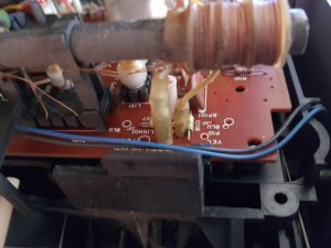
Looking inside from the rear of the radio, in the top left hand corner of the tuner board, there are two pins of two different diameters, not one, you have one missing, the cables to attach to these on the rear panel are one yellow and one white, you can't mix them up as they are also of corresponding diameters. So you are looking for five cables on the rear panel not four, three on the right side (blue, red, black) and two on the left (yellow, white)
Here's the only reference image I took while restoring my 8290 which is pretty much the same mainboard!
Sorry it's a little blurred but it shows where the wires definitely go!!
Sorry it's a little blurred but it shows where the wires definitely go!!
Attachments
-
 66 KB Views: 11
A los que necesiten imágenes de conecciones del interior de el TRK 8190 les puedo pasar. Tengo 2 de estos desarmados
Okay, so finally got some time and space to get this on the bench again and following the suggestions from @Superduper (many thanks) and have made some progress.
The capacitors tested good and it was a bit of a pain to get the heatsink covering C456 off. I might recap all these before putting it back. In hindsight this might not have been necessary (read on).
I decided to check the voltage feed to the tuner board by measuring the voltages on the 4 pin connector with brown and grey wires. This looked to be correct at ~6v but when I reattached the connector block to the tuner board the voltage dropped down to 2.5V.
I then decided to take IC301 out-of-circuit and the voltage feed to pin 1 rose back up to 6 volts (which is within spec for the chip) so I've ordered some replacements for the 2 ICs and am awaiting delivery.