Hello!
I am restoring a Sharp GF-555 that I got for a very reasonable price. So far I have fixed some usual suspects of this machine (bad belts, broken wiper in volume pot, e.t.c.)
Now however I have encountered a problem that I cant find the solution to. Speaker output of the machine is incredibly loud. It is excessively loud even when volume pot is at less than 1/4 of its travel. Also when radio is tuned to a station, the VU meters are in the red almost all the time. This leads me to believe that there is a problem in one of its amplifier IC`s and somewhere the signal level is too high.
I started to investigate this by inputting a 0,3V 1kHz sine wave signal into ''Line in'' of the unit. When probing ''Line out'' I got a 1,4V output signal. I feel this is strange, because I think that Line in and Line out output levels should be almost the same. Please correct me if I am wrong.
After that I moved my suspicion to ''IC 104'' which is a Rec & Line amp according to service manual. When probing its output pin I got an even higher 2.6 V signal level.
After this I tried to find a datasheet for this IC to maybe understand how the input gain is controlled. No luck here, there is no datasheet for this IC. All I could find was a block diagram of it. I am not an electronics expert at all, and this tells me very little about how the gain is controlled.
Can someone please advise if I am looking in the right direction, maybe these signals are as they should be. Also maybe someone has knowledge on how input gain is controlled for this preamp IC.
Any help is appreciated, Thanks!
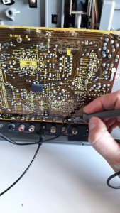
Probing ''Line out''
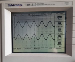
The results: CH1 is what I input to ''Line In'' and CH2 is output of ''Line Out''
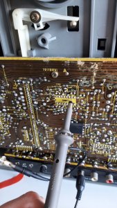
Probing output pin of IC104
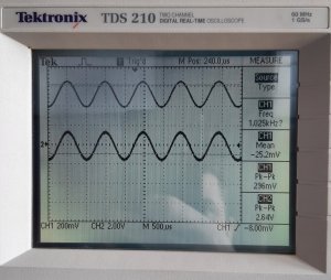
Results:
The IC in question in the schematic diagram:

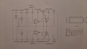
IC104 block diagram:
I am restoring a Sharp GF-555 that I got for a very reasonable price. So far I have fixed some usual suspects of this machine (bad belts, broken wiper in volume pot, e.t.c.)
Now however I have encountered a problem that I cant find the solution to. Speaker output of the machine is incredibly loud. It is excessively loud even when volume pot is at less than 1/4 of its travel. Also when radio is tuned to a station, the VU meters are in the red almost all the time. This leads me to believe that there is a problem in one of its amplifier IC`s and somewhere the signal level is too high.
I started to investigate this by inputting a 0,3V 1kHz sine wave signal into ''Line in'' of the unit. When probing ''Line out'' I got a 1,4V output signal. I feel this is strange, because I think that Line in and Line out output levels should be almost the same. Please correct me if I am wrong.
After that I moved my suspicion to ''IC 104'' which is a Rec & Line amp according to service manual. When probing its output pin I got an even higher 2.6 V signal level.
After this I tried to find a datasheet for this IC to maybe understand how the input gain is controlled. No luck here, there is no datasheet for this IC. All I could find was a block diagram of it. I am not an electronics expert at all, and this tells me very little about how the gain is controlled.
Can someone please advise if I am looking in the right direction, maybe these signals are as they should be. Also maybe someone has knowledge on how input gain is controlled for this preamp IC.
Any help is appreciated, Thanks!
Probing ''Line out''
The results: CH1 is what I input to ''Line In'' and CH2 is output of ''Line Out''
Probing output pin of IC104
Results:
The IC in question in the schematic diagram:
IC104 block diagram: