Fixing a Mystery Ebay Legend
- Thread starter stragulus
- Start date
- Status
- Not open for further replies.
Yeah that is part of the spare cassette storage tray, which you do not have..so, therefore it is not needed!stragulus said:What's this magic part? It was under the black chassis. I took a billion pictures before I got to that part, but it's not on any of them. Looks like it was there already before I took it apart. What could it be? Maybe part of the tape door mechanism..?
It gets dirty easy because there is a factory grease on there that collects dust.. That piece acts as a pivot along with a spring to lock in and eject the spare tape drawer..
That looks like such a bargain at $80, as others have said theres massive improvement already just by cleaning it.
Hope you get it mechanically sorted aswell
Hope you get it mechanically sorted
aswellSo I got the beast on my workbench and have traced the audio signal to a point right after the function selector where it enters a couple of small transistors near the volume pot. It dies there.
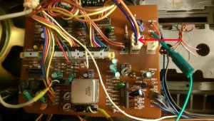
I wonder if it's related to the weird power distribution in this thing. Two power lines come from the small pcb that houses the power and burglar alarm button. One goes to the top amp board and reads 13V when on and 0V when off. Seems sane. The other one however, goes to a small pcb next to tape 1. That one reads slightly below 20V when on, and 21V when switching power off (using the power button). Wut? That can't be right.. there's a cap next to it that has a max rating of 16V! The red arrow points to the 20V line.
Power to the pre-amp board seems to originate from this pcb. Voltages across the pre-amp pcb are all suspiciously low. Maybe OK due to it being mostly passive circuitry, but given that weird 20V reading I suspect there's something wrong. A service manual really would help here, but I can't find any. Would anyone here have one perhaps that I could take a sneak peek at?
I'm onto something. There's a preamp IC on the preamp board that should get anywhere between 6-16V but only gets 0.7V. So does indeed look like the voltage to this board is wonky.
Also, feeding this thing AC power doesn't seem so good for its longevity. It sends 20V to the amp chips when using AC power, which is its absolute maximum rating, for one thing. It's only 15V on batteries or DC, the recommended maximum. No surprise these things blow. I think when/if I get this thing fixed, I'll replace the ac power section.
Also, feeding this thing AC power doesn't seem so good for its longevity. It sends 20V to the amp chips when using AC power, which is its absolute maximum rating, for one thing. It's only 15V on batteries or DC, the recommended maximum. No surprise these things blow. I think when/if I get this thing fixed, I'll replace the ac power section.
ALL classic boomboxes have unregulated supplies and it's not uncommon at all to get 20+ volts on a 15v rated AC supply, especially when under a no-load condition. In my experience, most all voltage sensitive circuitry such as tuners & IC's and digital circuits will be powered after a voltage regulator and if you see any Zener diodes present, they most certainly are part of the regulators.
Good to know! I was really worried there. Looks like the power going to the top amp board is only used by the amps and is the unregulated feed (amps being not too critical I guess). All other power comes from the secondary power line that is routed to the small pcb next to tape 1. Looks like it's being regulated there and split into 2 different feeds, one of which does indeed go to the tuner, and should probably also go to the preamp board.
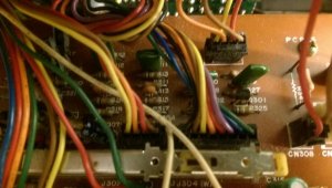
I have proof, beyond a reasonable doubt, that whoever designed this box HATED engineers. With a passion. Just look at the 2 4-pin connectors in the picture below. Notice anything odd? Yeah, they both have EXACTLY the same colors. Additionally, they *both* go to the same preamp-board, pretty close together. And there's no way to tell which one goes where either once disconnected. Unless, of course, you took pictures.
Well, luckily in my case I didn't disconnect them at all, so I know which one goes where. I did verify that someone else didn't accidentally switch them.
Well, luckily in my case I didn't disconnect them at all, so I know which one goes where. I did verify that someone else didn't accidentally switch them.
What you say is completely true. 100%. Also there is NO service manual either so the manufacturer probably intended all warranty service of significant issues to be returned? Unlike major manufacturers whose products and service procedures are well documented, there only exists a schematic (like you would find with the old transistor handheld radios of the '70's). Also many manufacturers of output amp modules include a manufacturer suggest sample circuit in their data sheets and the HA1392 chips used in this BOOMBOX are no different in this regard. In it, you'll see that 1000uf output caps are used and recommended in SE configuration. No sample bridged configuration is included. However, in my experience, when such amp modules are bridged, the output caps are omitted and not used (such as on the Pioneer SK-900) and that pioneer sure is a sweet sounding radio. THIS boombox bridges those hitachi chips and retains the output caps. I'm not saying that the engineers messed up but I will that I've never seen bridged amps with those caps included in the circuit before. Also iirc and unless I'm mistaken, the bridging crisscrosses with the opposite module.
In any event, since you suspect the preamp board is not getting proper power, maybe check and see if any regulators are blown?
In any event, since you suspect the preamp board is not getting proper power, maybe check and see if any regulators are blown?
Superduper, I'm certainly no expert in circuit design, so I'll have to take your word for it! But I've worked on a couple of other boxes, and even without service manuals they were much easier to take apart and to troubleshoot. Logical color coding, helpful descriptions on the pcb's with clearly identified functional sections, etc. And certainly not this giant cable mess!
So I've spent a lot of time tracing the source of the power to that IC's Vcc pin. I've never "debugged" a circuit like this without a service manual, but it was a very interesting experience that taught me a lot already. I have now traced the source to a connector on the pcb with the big amp chips on them. When I disconnect this connector, and turn the box on, one of the pins measures 12V. On the connector, this leads straight to the IC's Vcc pin, and is routed to various other parts of the box. With the connector connected, it drops to 1.1V, so clearly something's wrong there as suspected. I think I'm close to finding the culprit now
So I've spent a lot of time tracing the source of the power to that IC's Vcc pin. I've never "debugged" a circuit like this without a service manual, but it was a very interesting experience that taught me a lot already. I have now traced the source to a connector on the pcb with the big amp chips on them. When I disconnect this connector, and turn the box on, one of the pins measures 12V. On the connector, this leads straight to the IC's Vcc pin, and is routed to various other parts of the box. With the connector connected, it drops to 1.1V, so clearly something's wrong there as suspected. I think I'm close to finding the culprit now
 I found an open zener diode on that voltage line.
It's an 11v Zener. The wattage you can determine from the physical size of the diode. That driver might be 2SD325 or it might be the component enumeration number for that semi -- I would go by whatever is imprinted on that transistor body but it's not a critical transistor since it's merely a voltage regulator. I would probably go with a more robust transistor (I'm presuming it's an NPN).
 :gathering: :superduper:
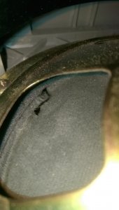
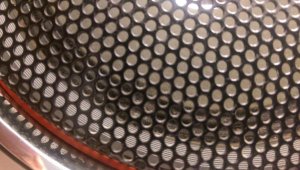
Crap! I dropped my test lead in the worst possible way  I heard the sound, and was instantly mortified:
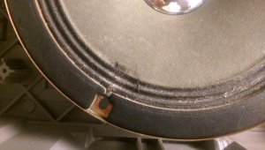
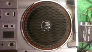
I salvaged it by carefully applying black silicone caulk to the backside:
Still mad at myself, but it could be worse. Careful, careful, careful..
I heard the sound, and was instantly mortified:I salvaged it by carefully applying black silicone caulk to the backside:
Still mad at myself, but it could be worse. Careful, careful, careful..
Oh no!!!stragulus said:Crap! I dropped my test lead in the worst possible way
IMAG3048 speaker punctured.jpg
I salvaged it by carefully applying black silicone caulk to the backside:
IMAG3068 speaker fixed.jpg
Still mad at myself, but it could be worse. Careful, careful, careful..
That hurts! I always cover the speaker back with paper and tape it. In most cases something would fall and make a tear or screws will go inside and get stuck there near the magnet. I cover the front of speakers also after messing up the dust cap of my M70. I was cleaning the speaker cone paper and then shined dust cap, but a tiny screw from my hand slipped off and made an ugly dent on the nice dust cap. I used suction to pull it out and made one more dent nearby. I was so upset.....gave up all my work and did nothing for the rest of the day.
Now I don't see all the other nice things of my beautifully working M70 but see only that dent on the dust cap.
Yeah I share that feeling with you  Even though it won't have any effect on the sound and you don't even see it behind the speaker grills, it's still the feeling that you stupidly ruined something. I gave up doing anything after that also. I'm now definitely covering up the speakers when I need to work on it in the casing.
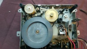
Since then I have worked on the tape decks. Belts had turned into goo on deck 1. Replaced one, ordered a flat belt for the flywheel drive belt. Deck 2's belt was an easy swap. Additionally, I cleaned all the buttons and switches. Carefully cleaned the chrome speaker centers with a q-tip so that they shine again. Properly re-attached tape 1's door in the case. The case misses 1 plastic stub on which the door hinges, but with the spring re-attached it stays in place well enough. If I can think of something I'll fix it properly some day.
I'm trying to figure out what to do about the missing spare tape drawer. I normally like to keep the boxes in their original state, but in this case, since I'm missing it altogether, I'm contemplating adding something flashy that fits with the style of the boombox. Maybe 2 rows of rgb leds being driven by an arduino microprocessor hooked up to line-out? I could have a drawer 3d-printed for that and then add the leds + board inside. Something to think about. Meanwhile I'm impatiently waiting for delivery of the replacement transistor to see if that will bring it back to life
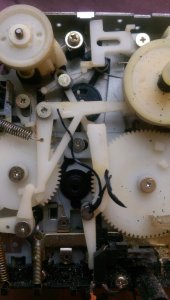
Even though it won't have any effect on the sound and you don't even see it behind the speaker grills, it's still the feeling that you stupidly ruined something. I gave up doing anything after that also. I'm now definitely covering up the speakers when I need to work on it in the casing. Since then I have worked on the tape decks. Belts had turned into goo on deck 1. Replaced one, ordered a flat belt for the flywheel drive belt. Deck 2's belt was an easy swap. Additionally, I cleaned all the buttons and switches. Carefully cleaned the chrome speaker centers with a q-tip so that they shine again. Properly re-attached tape 1's door in the case. The case misses 1 plastic stub on which the door hinges, but with the spring re-attached it stays in place well enough. If I can think of something I'll fix it properly some day.
I'm trying to figure out what to do about the missing spare tape drawer. I normally like to keep the boxes in their original state, but in this case, since I'm missing it altogether, I'm contemplating adding something flashy that fits with the style of the boombox. Maybe 2 rows of rgb leds being driven by an arduino microprocessor hooked up to line-out? I could have a drawer 3d-printed for that and then add the leds + board inside. Something to think about. Meanwhile I'm impatiently waiting for delivery of the replacement transistor to see if that will bring it back to life
lt may be the part for the missing drawer, or the pause activator..does the pause button function and lock?stragulus said:What's this magic part? It was under the black chassis. I took a billion pictures before I got to that part, but it's not on any of them. Looks like it was there already before I took it apart. What could it be? Maybe part of the tape door mechanism..?
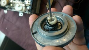
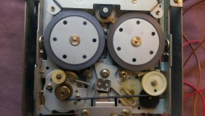
When you remove that flywheel make sure you saved that tiny teflon or high melt point plastic washer in the front of the oilite sleeve bearing (oilite bronze bushing) and the capstan at the cassette loading side. That is so hard to find if you lose it. In most cases it gets stuck to the sleeve bearing.
- Status
- Not open for further replies.