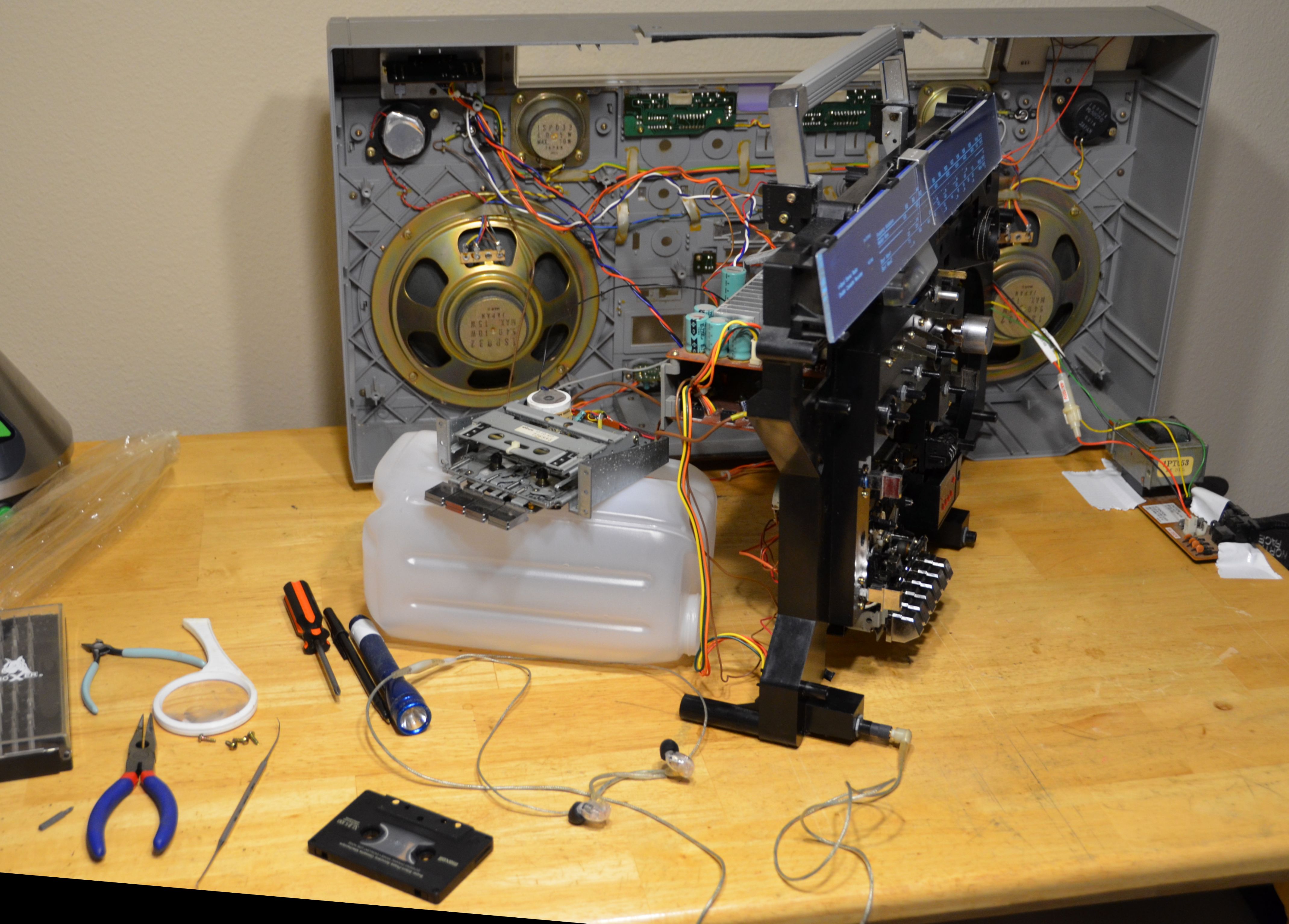
I thought I'd share how I upgraded the dial light for our highly valued member DAFUZZ. I took advantage of the situation to try a new approach to the wiring over what I did in my C-100F restoration last year.
On one hand I am glad I rewired my box to work on batteries, mains or wall wart, and it does look great, but it will start to blink in and out if the bass starts kicking. It also involved some amount of rework on the switch board to feed 15VDC to the dial board instead of the default 7VAC from the transformer.
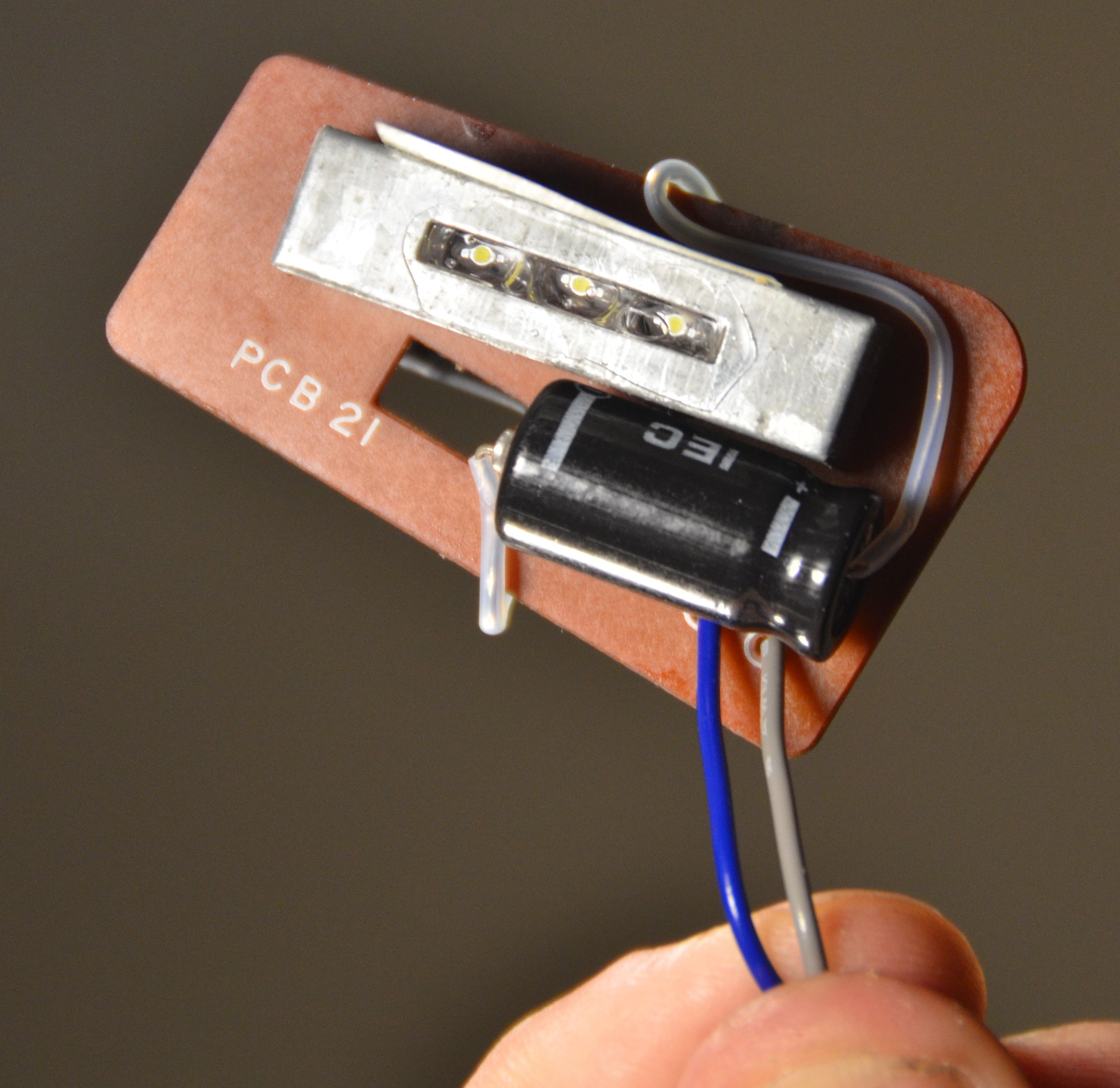
This time I decided to keep using 7VAC to avoid dropouts, and build a little rectifier circuit out of four 1N4002 diodes and a cap, giving me about 8.5VDC. Using three LEDs rated at 3.2V/20mA, the resistance I was given by this site was 270 ohms, but when it's in the circuit, it only measured about 7.5mA, but it's still very bright. I also applied some aluminum tape on the far end for more even light.
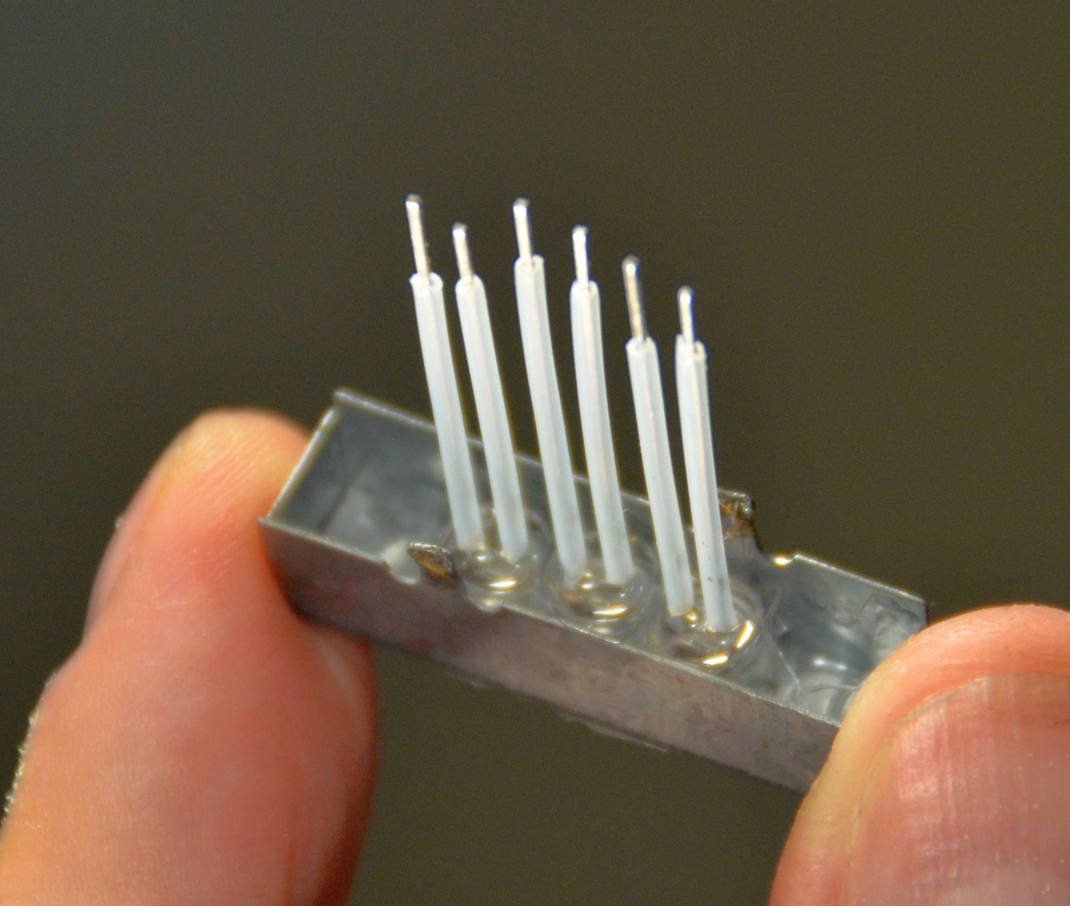
I used the edge of a diamond cutting wheel to cut a groove in the board for the LED leads to stick through to the back side, and then used a couple of drill bits to even it out. A little R6000 to glue the LEDs into place with some tape (the non-sticky side) over the slit to ensure the glue cured with a smooth surface.
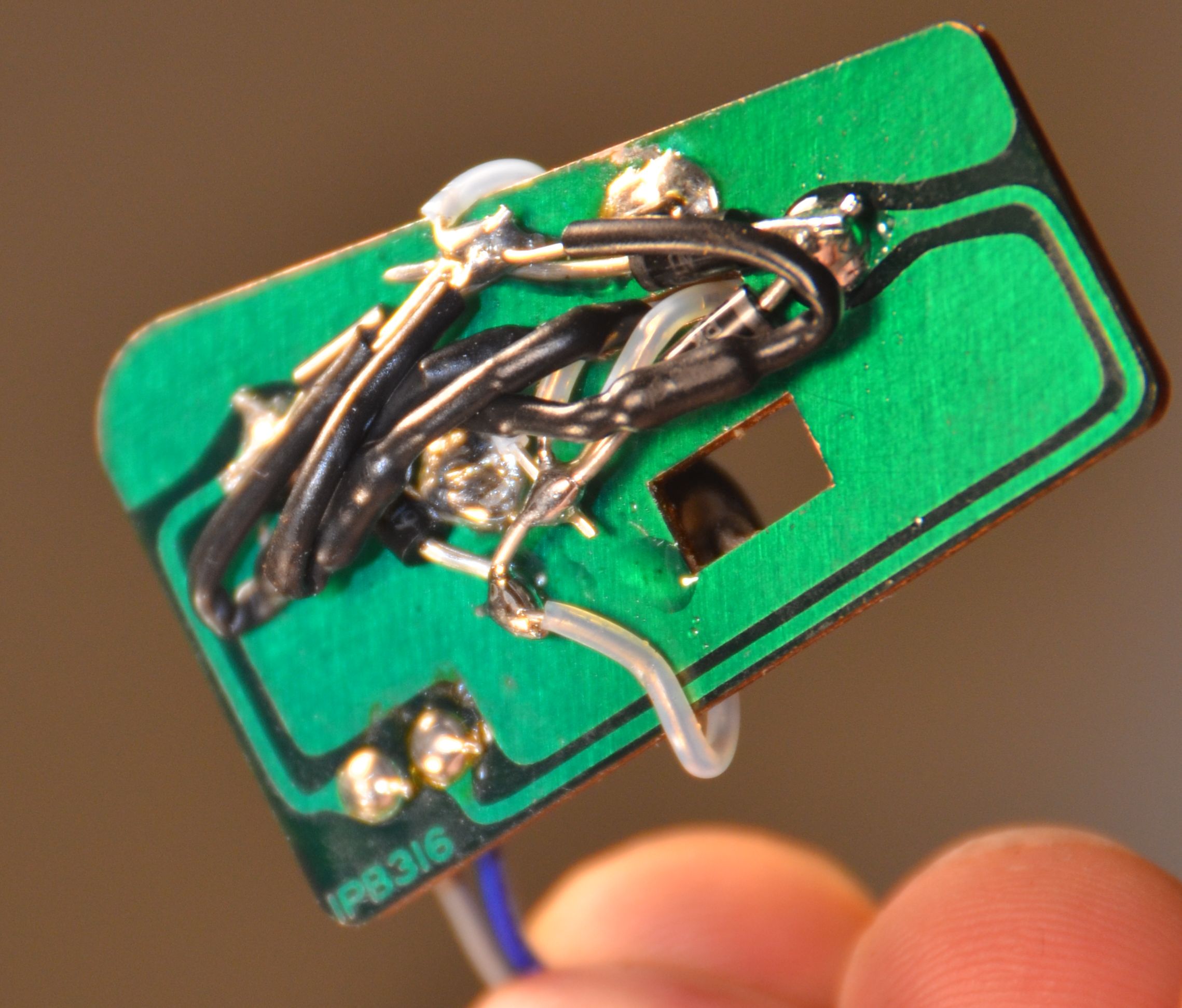
After a lot of soldering, nylon tubing, shrink tubing and burnt fingertips, we have a winner that just BARELY fit. I'm almost thinking it got pushed a bit by the switch board mounting plate, but everything is insulated and seems to be working fine")
PS - Sorry about the big band music, I picked up a pile of cassettes at Goodwill for testing, haha!
But first, some new belts for the decks...


https://www.youtube.com/watch?v=cqp2ApiyTcU
On one hand I am glad I rewired my box to work on batteries, mains or wall wart, and it does look great, but it will start to blink in and out if the bass starts kicking. It also involved some amount of rework on the switch board to feed 15VDC to the dial board instead of the default 7VAC from the transformer.
This time I decided to keep using 7VAC to avoid dropouts, and build a little rectifier circuit out of four 1N4002 diodes and a cap, giving me about 8.5VDC. Using three LEDs rated at 3.2V/20mA, the resistance I was given by this site was 270 ohms, but when it's in the circuit, it only measured about 7.5mA, but it's still very bright. I also applied some aluminum tape on the far end for more even light.
I used the edge of a diamond cutting wheel to cut a groove in the board for the LED leads to stick through to the back side, and then used a couple of drill bits to even it out. A little R6000 to glue the LEDs into place with some tape (the non-sticky side) over the slit to ensure the glue cured with a smooth surface.
After a lot of soldering, nylon tubing, shrink tubing and burnt fingertips, we have a winner that just BARELY fit. I'm almost thinking it got pushed a bit by the switch board mounting plate, but everything is insulated and seems to be working fine
PS - Sorry about the big band music, I picked up a pile of cassettes at Goodwill for testing, haha!
But first, some new belts for the decks...
https://www.youtube.com/watch?v=cqp2ApiyTcU
 I can't believe You did that for Me. Mega Thanks, Brother. It was so cool hanging out with You and shooting the sh!t for hours. We gotta do it again, and have more beers.
 Thanks Eric.


 This is the correct way of LED modification.
  That looks nice!