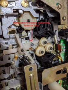
The mechanism for the deck in this boombox has a clutch assembly in the fwd/rwd drive. This assembly provides slippage when the tape is at the start or end so that the box will not break your tape.
Now while this deck's mechanism is pretty beefy for a boombox with lots of heavy steel parts and linkages, the clutch assembly sadly relies on plastic parts to stay together. Plastic parts that, as they age, shrink. Inevitably, due to the design, this will break the assembly. I Doubt there's a boombox of this type around today that still has this functioning well, but who knows they may have used different materials for different revisions.
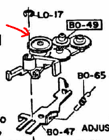
Anyway, an illustration of how this assembly works will help explain the attempted repair. The different parts are:
My attempt to fix this, is to replace the lego-like joint (there has to be a better term for this?) with epoxy glue. The parts that are joined together do not rotate relatively to each other, so this does not impact the function of the clutch assembly. To get the glue to set, things need to be clamped together, which needs some custom made jigs to keep everything in place the right way.
The pictures of all the various parts and jigs with some inline explanations:
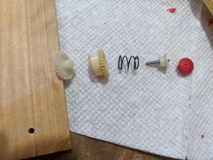
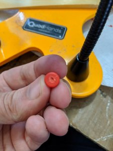
All of the clutch assembly parts in the right order. The red plastic cap at the right is part of tthe jig. Notice how it has a little dimple in the middle? That is there to keep the jig in place as we clamp it. It cannot be a full hole as then the pin will not be restrained in place, which is very important. It must completely stick out the bottom end!
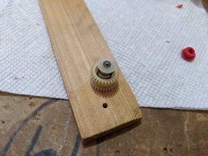
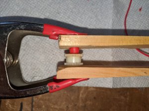
All the clutch parts assembled before the clamping. Notice the hole in the piece of wood (the other part of the jig). This is necessary as, when everything is clamped together, the pin will protrude from the bottom. Yet we still want to clamp it in place easily so now it can sit in this little hole.
This is how everything will be clamped together once the glue is applied. The spring sits inside now:
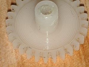
The bottom gear. The outside of the shaft is what needs to be glued. Notice in one of the pictures above that there's a plastic white cap on the pin. That cap slides onto this shaft here. When this was new, apparently this was a snug enough fit to not need glue to stick together. Now, not so much anymore!
I have made some grooves into the shaft's outside with a sharp blade, to hopefully better adhere to the glue. Care must be taken to not get glue on the horizontal plane of the gear as that is where the felt of the top gear sits on, and that should actually be able to rotate.
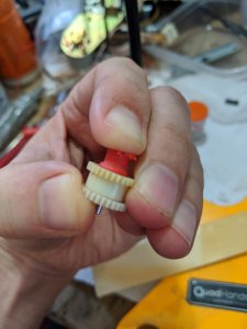
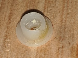
The plastic cap where the top part of the pin slides through. You can barely make it out but it is partly torn, causing the malfunction.
And here it is, all clamped together after applying the glue (I used JB Plastic weld, a 2 component epoxy). Let's just keep that in place for a day.
What do you think... will it work? I give it a 4 out of 10 chance.
Now while this deck's mechanism is pretty beefy for a boombox with lots of heavy steel parts and linkages, the clutch assembly sadly relies on plastic parts to stay together. Plastic parts that, as they age, shrink. Inevitably, due to the design, this will break the assembly. I Doubt there's a boombox of this type around today that still has this functioning well, but who knows they may have used different materials for different revisions.
Anyway, an illustration of how this assembly works will help explain the attempted repair. The different parts are:
- A bottom gear. This directly drives one of the 2 reels to rwd/fwd.
- A top gear. This one is driven by a gear on the main flywheel, which in turn is driven by the motor through the main drive belt
- A pin (axis?) running through both gears with a plastic cap on top to keep it in place
- A spring that pushes the top gear onto the bottom gear - this provides enough tension to make the bottom gear rotate when the top gear is driven, but when the bottom gear stops because the tape is at the end, the top gear will slip (there is felt in between the gears) to prevent all the driving force from putting too much tension on the bottom gear.
My attempt to fix this, is to replace the lego-like joint (there has to be a better term for this?) with epoxy glue. The parts that are joined together do not rotate relatively to each other, so this does not impact the function of the clutch assembly. To get the glue to set, things need to be clamped together, which needs some custom made jigs to keep everything in place the right way.
The pictures of all the various parts and jigs with some inline explanations:
All of the clutch assembly parts in the right order. The red plastic cap at the right is part of tthe jig. Notice how it has a little dimple in the middle? That is there to keep the jig in place as we clamp it. It cannot be a full hole as then the pin will not be restrained in place, which is very important. It must completely stick out the bottom end!
All the clutch parts assembled before the clamping. Notice the hole in the piece of wood (the other part of the jig). This is necessary as, when everything is clamped together, the pin will protrude from the bottom. Yet we still want to clamp it in place easily so now it can sit in this little hole.
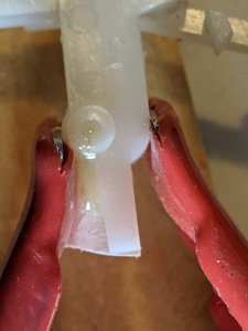
This is how everything will be clamped together once the glue is applied. The spring sits inside now:
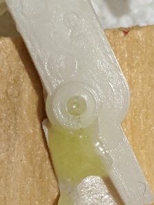
The bottom gear. The outside of the shaft is what needs to be glued. Notice in one of the pictures above that there's a plastic white cap on the pin. That cap slides onto this shaft here. When this was new, apparently this was a snug enough fit to not need glue to stick together. Now, not so much anymore!
I have made some grooves into the shaft's outside with a sharp blade, to hopefully better adhere to the glue. Care must be taken to not get glue on the horizontal plane of the gear as that is where the felt of the top gear sits on, and that should actually be able to rotate.
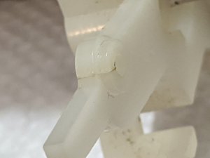
The plastic cap where the top part of the pin slides through. You can barely make it out but it is partly torn, causing the malfunction.
And here it is, all clamped together after applying the glue (I used JB Plastic weld, a 2 component epoxy). Let's just keep that in place for a day.
What do you think... will it work? I give it a 4 out of 10 chance.
Attachments
-
 368.2 KB Views: 6
Last edited: