M90 Successful Deck Repair HOW TO

Lasonic TRC-920

Moderator
Feb 16, 2010
14,130
107
48
55
Naples, Italy
Below is a description of the repair process for my M90 deck. By no means will this be the "Fix All" for every deck, but you should be able to follow these instructions to at least check these problems off your list.

A HUGE shout out to Boomboxery member DOCS for walking me through this process at great cost to his time. I can't thank him enough.

To start with, your going to need the M90 service manual available at http://www.analogalley.com/. This is a tiny investment that will pay for it's self once you have a fully working M90 should you ever choose to sell your radio.

My radio's symptoms:

Line in and Radio were fully functional. The deck was completely dead with a cassette stuck inside. When pushing the power button, an audible CLUNK was heard. None of the buttons, FFW, REW or Play worked. The music search lights did come on, but nothing happened with the deck.

I was able to locate two distinct problems with my deck that I think are common problems, one that may have led to the other and caused the failure.

Repair Part 1:

Remove the back of the radio (without it being plugged in!)
Remove 5 purple screws that hold the deck in the back of the unit (4 short, one long)
Unplug all the connections going to the deck. There will be a series of grey wires that can not be unplugged. This is not an issue, leave them connected, they are long enough to pull the deck from the radio and service it.
Re-belt if needed (recommended). Belt info here. There is nothing tricky here, 3 belts, easy to get to.
In the JVC service manual "Supplementary" section, on page 2 you will find the "Mechanical Control P.W.B. Parts" diagram and on page 3 you will find the parts list.
The components you are looking for are FR701, FR702, FR703 and FR704. These are "Fusible Resistors". They are designed to "Pop" like a fuse to prevent damage to other components. This is a common point of failure on this radio and built into it's design.
Remove the 4 small screws that hold the PC board to the back of the deck mechanism. Be careful with all these components.
Using a multi meter, you want to check the values of component FR701, FR702, FR703 and FR704. These are OHM measurements. The location of these fusible resistors are in the diagram on page 2 of the service manual.

IN MY CASE I was able to locate FR704 as being burnt. It tested DEAD on the multi meter and was visually "cooked" and dark in color compared to the other 3 fusible resistors.

This is the fusible resistor that was burned on mine.
Resistor replaced.png

NOTE: the four fusible resistors are different values. two are 4.7ohms, one is 10 and the other is 2.2.

I chose to replace ALL FOUR fusible resistors with new ones. I bought them from https://cpc.farnell.com/ They were CHEAP! I bought extra's, 10 of each, it was £5.76 (in British Pounds) delivered (in the UK).

One at a time, I un-soldered, removed and tested each fusible resistor. Confirming the one that was burnt and the values of the 3 I was replacing to make sure they matched what I was putting back in with the new ones I bought. Once confirmed, I reinstalled. This was very easy.

Repair Part 2:

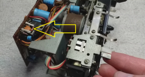
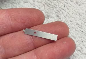
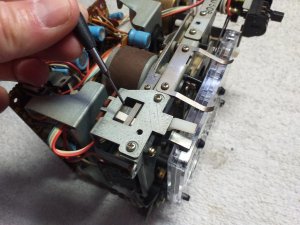
Once the fusible resistors were installed I found a small component laying on my work bench under the deck. This small component was part of a leaf switch assembly that I believe was the ACTUAL problem with the deck that caused the fusible resistor to blow.

IMG-20190412-WA0002.jpeg

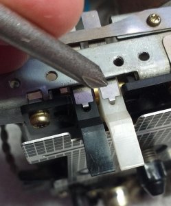
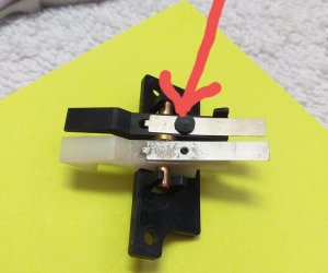
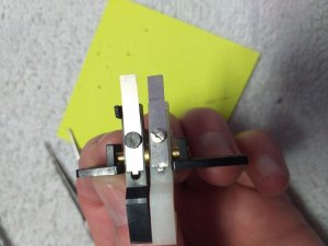
This piece is part of the lever switch that tells the deck if there is a cassette in the carriage tray (white). It is located right next to the switch that tells the deck if the tape that is inserted can be recorded on (black).

Switch arrow.pngIMG-20190412-WA0004.jpeg

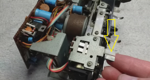
In my case, the metal part of the switch became detached from the plastic part (white). This meant that when the cassette was inserted in the deck, the switch was not pushed, letting the deck know there was a cassette in the tray. It is this reason that I believe the fusible resistor may have blown (hypothetical). Testing this switch with a multi meter would be a good isea, even if your switch is not broken. Test with out a cassette in the tray and then with one in the tray and see if the switch is working.


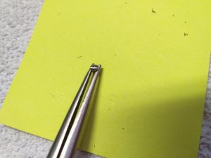
In my case, this little button that holds the metal part to the plastic part popped off.

20190412_155832.jpg

The metal part is under pressure when engaged and will not hold with glue.

I modified a micro machine screw to re-attach the two pieces.
20190412_164508.jpg20190412_164519.jpg

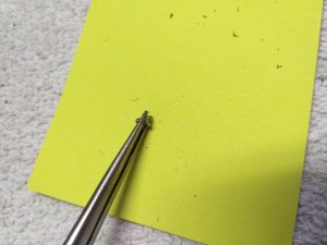
I then hand drilled out the original plastic holder shaft.
20190412_164032.jpg

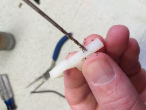
I then put the screw in place to hold the parts together
20190412_165531.jpg

It is important that the "Button Head" of the screw be the same thickness of the "Button head" of the plastic piece on the other switch. This was 0.45mm. I used a dremil to grind the screw head to the correct thickness. I then cut a slot in the head of the screw for a screw driver.

Everything was then reassembled. The switch should be level with the switch next to it and operate freely.

20190412_165837.jpg

I reassembled everything and the deck worked the first time.

Hopefully this will help other get their M90 decks working. Good luck.
 

im_alan_partridge

Member (SA)
Jul 21, 2010
2,976
1
38
London, England.
Various m90 deck issues must have been one of the biggest roadblocks and deadends I have read about on the boards, often leaving owners utterly disillusioned.
Although I don't have an m90 this guide and pics is interesting reading and will be a great resource for the future.
 

Lasonic TRC-920

Moderator
Feb 16, 2010
14,130
107
48
55
Naples, Italy
im_alan_partridge said:
Various m90 deck issues must have been one of the biggest roadblocks and deadends I have read about on the boards, often leaving owners utterly disillusioned.
Although I don't have an m90 this guide and pics is interesting reading and will be a great resource for the future.
What I know about M90 deck's is what you just read. Beyond this, I wouldn't know where to go. BUT, after lengthy conversations with DOCS, me describing it's behavior (clunk on power up, no reaction from the buttons), and him giving me components to check, this is how/why he suggested looking at the fusible resistors first.

Keep in mind, the fusible resistors are designed to blow to prevent damage to other components. They are also a sign of an issue if they have blown. So, in theory, simply replacing the resistors and not finding the cause of them blowing in the first place, isn't going to solve the problem. To be honest with you, it was dumb luck I found that loose switch lever on my work bench, it was also dumb luck I was able to figure out where a totally random piece went.

But I do think checking that switch to see if it is functioning and testing the fusible resistors is a solid place to start! Once those are checked off the list, you can move forward and this is something all of us can do.
 

Northerner

Member (SA)
Apr 16, 2012
5,323
255
83
North West UK
I wonder if that’s the problem with mine? It just blew the resistor again once replaced so there’s something making it blow. I’ll have a look.
 

docs

Member (SA)
Jun 26, 2010
2,558
381
83
52
United Kingdom
Great Chris, so happy with this fix.
Took a bit of making sure no other components were blown and then the shipping of those resistors from cpc-me-italy was destined to break but alas, they arrived.
Well done!!!
Enjoy that beast!
 

T-STER

Member (SA)
Jul 14, 2014
2,246
73
48
UK
Great team work, this is so good to see. And so happy you ended up with a working deck!
 

deech

Member (SA)
Jan 11, 2012
680
304
63
Athens Greece
Great work as always Chris, full of helpful tips and detailed pictures that show the procedure step by step.
Congratulations to both of you cris andocs for making the deck work again.
 

Lasonic TRC-920

Moderator
Feb 16, 2010
14,130
107
48
55
Naples, Italy
Hisrudeness said:
Yes that Doc’s fella is pretty good at helping with telephone repairs. Once helped me fix a Big Ben deck via WhatsApp.

Great to see it all tip top.
It's amazing what can be done through test messaging! Thanks bro

Northerner said:
I wonder if that’s the problem with mine? It just blew the resistor again once replaced so there’s something making it blow. I’ll have a look.
A quick test of that switch will let you know. Please post back in this thread what you find out. :yes:

Superduper said:
That's awesome Chris. If everyone that had issues with their M90 deck would first replace belts and look at those fusible resistors (or replace them) while they're in there, I'll bet that would eliminate 90% of the "help" requests out there.
I bet your right. As a person that has never worked on the M90 deck before, and knowing that this unit is seen as this "Super High End, bla bla bla" I just assumed it would have 10 belts, 20 adjustment points and alignment issues, basically be way over my head. And before I even opened it, just in a conversation with Hisrudeness, he told me "Yeah, there are only three belts, it's not a big deal". After that, I didn't mind opening it.

QUESTION: Is it possible to blow the fusible resistors if the belt is slipping or broke?

docs said:
Great Chris, so happy with this fix.
Took a bit of making sure no other components were blown and then the shipping of those resistors from cpc-me-italy was destined to break but alas, they arrived.
Well done!!!
Enjoy that beast!
Thanks for helping me get those resistors shipped to Italy. That was the hardest part :lol:

Seriously though, thanks for all your time and effort. I don't know how many of these you have been through. Seems like allot. But I don't think I could have done it with out you!

caution said:
Nicely done Chris! These decks are a BEAST to work on.
I think you have torn this deck down further than anyone outside of JVC. They aren't a horrible design, not like an Aiwa :lol: It helps that I took it apart and put it back together again 20x :-P

T-STER said:
Great team work, this is so good to see. And so happy you ended up with a working deck!
Thanks T, the planets really did line up for me on this. From Katsa working with me and doing such an amazing job shipping, to being an American European :lol: and getting to meet DOCS personally and him helping me work this out. :lol: Pretty damn lucky I would say.

deech said:
Great work as always Chris, full of helpful tips and detailed pictures that show the procedure step by step.
Congratulations to both of you cris andocs for making the deck work again.
Thanks Deech, the only way to make the dream of classic boombox ownership possible is through teamwork! :clap:

Here is how the story ACTUALLY went. Night after night, DOCS and I would get on WhatsApp. We each own a copy of the Service Manual that we bought from http://www.analogalley.com/. This was hugely important, because we could both look at the same information at the same time.

DOCS found a starting point on the deck PC Board, called out a component number, located it on the PC Board, took an up close picture of the schematic, circled the component I was to look for and sent it to me. I then located that component, he then called out what it's "tested value" should be and I tested it with the multi meter. And so we went down the line. One item at a time, to make sure that it wasn't just the fusible resistor that was blown and not a far bigger problem. We traced each line through the board, before and after the fusible resistors (x4).

This took hours and hours over multiple days.

I learned a few things here.

1) That we are lucky to have these service manuals. It has all the information needed to do this kind of work. (tons of radios have manuals for them)
2) How to locate the item in the service manual, find it on the board and then find it's value in the service manual and test it.

**I know there are allot of collectors like myself that shy away from this kind of work, but figuring this out will open doors for repairing you dream boxes! Highly recommended.

3) That DOCS isn't just a pretty face! :w00t: :yes:
 

caution

Member (SA)
Mar 25, 2014
2,508
343
83
Boomboxery
Lasonic TRC-920 said:
QUESTION: Is it possible to blow the fusible resistors if the belt is slipping or broke?
It's very possible. The timing chart says the solenoid will activate if the drive gear is between 0 and 3/4 turn. If you turn it on and it's in that region, it will make sure to turn the gear until it's reset and the heads are down. So if the flywheel belt is shot, the gear won't be able to move out of the activated zone, and if it can't do that, the deck IC won't get a signal from the opto sensor saying the gear is in a reset position. And if THAT doesn't happen, the deck IC won't disable the control transistor gating the solenoid's path to ground.

FR704 is only 4.7 ohms, so at 15+ volts that's up to 3 amps (or whatever the limit of the control transistor is), which could put excessive drain the batteries and possibly overheat them. Or overheat the solenoid. Better to overheat a cheap replaceable resistor.
 

Lasonic TRC-920

Moderator
Feb 16, 2010
14,130
107
48
55
Naples, Italy
caution said:
QUESTION: Is it possible to blow the fusible resistors if the belt is slipping or broke?
It's very possible. The timing chart says the solenoid will activate if the drive gear is between 0 and 3/4 turn. If you turn it on and it's in that region, it will make sure to turn the gear until it's reset and the heads are down. So if the flywheel belt is shot, the gear won't be able to move out of the activated zone, and if it can't do that, the deck IC won't get a signal from the opto sensor saying the gear is in a reset position. And if THAT doesn't happen, the deck IC won't disable the control transistor gating the solenoid's path to ground.

FR704 is only 4.7 ohms, so at 15+ volts that's up to 3 amps (or whatever the limit of the control transistor is), which could put excessive drain the batteries and possibly overheat them. Or overheat the solenoid. Better to overheat a cheap replaceable resistor.
OK, This is very important information here. When I opened this deck, the main flywheel drive belt was off the flywheel. It was old and stretched. Katsa said the deck did work some time back. So it's totally possible that the loose belt jumped the fly wheel and over heated the resistor. I have no idea WTF was up with that busted switch though :lol: All speculation of course.
 

Superduper

Member (SA)
Lasonic TRC-920 said:
QUESTION: Is it possible to blow the fusible resistors if the belt is slipping or broke?
Absolutely. The fusible resistor that you show is probably FR704, which is the most common toasted resistor. That's because it supplies current to the power hungry solenoid. Ordinarily, that solenoid only works momentarily, the longest of which is triggered by play function, and even that is only for 3/4 of ONE revolution. The rest are only a fraction of that. What happens is that the capstan motor is spinning but that doesn't trigger any action other than for it to freewheel. In order for the head carriage to come up, and the proper gear mechanisms to mesh into the proper position, the solenoid needs to trigger that function. Anyone that has ever spun a flywheel manually to "reset" it knows what I'm talking about. It only takes less than 1 revolution to accomplish this task. And of course there is a torque hump to overcome too, so this whole process takes more current than normal, but it's only expected momentarily. If a belt is slipping, it almost always causes extended cycle times, or worse, forever cycle time. Since fusible resistors aren't really fuses, but are actually resistors that always operate on the threshold of their heat limits, they will burn up when they supply excessive (power). Power because they are rated in watts, not voltage or current, but the "product" of VA.

Ordinarily, when fuses are blown, it is of paramount importance to first identify the cause of the blown fuse before replacing it. In most cases, replacing a blown fuse without first identifying the original cause almost always results in additional circuitry failures beyond the original failure. However fusible resistors are a bit different. Remember, fuses usually are rated in current (A). Fusible resistors are rated in watts. Usually, these resistors will begin to change value over time even with normal usage simply because they always run sort of hot to begin with. Then if belts are slipping, it adds to the problem. In most cases, installing fresh belts and replacing any bad or out of spec fusible resistor will restore the deck to proper operation. You said you feared a complicated deck but was pleasantly suprised to see it was nothing special. The normal service most definitely is that. It is an easy deck to remove and service. But the control circuit is anything but simple. On the deck board itself, you'll see something like a dozen transistors, not to mention tons of diodes and logic IC's and a couple of dedicated control IC's. If anything there becomes amiss, then the repair is indeed in another class level and not a simple fix. Luckily, the circuit was designed well and it simply works. Rarely does anything besides the fusible resistors fail. If you'll notice, there is no mechanical switching, all is done via solid state (transistors & IC's). There is no record bar... all of the record bar switching functions is via that deck board electronics.

Anyway, when servicing this deck, it is very important to keep the following in mind:
  1. Replace bad resistors with the proper wattage. 1/4 watt resistors are specified. It is tempting to go higher wattage to prevent future blown resistors but it may cause other circuit failures. In other words, if that resistor doesn't fail when it should, maybe you'll have toasted transistors or regulators, or motors, or solenoid.
  2. Replace bad fusible resistors with "fusible" resistors whenever possible. However, as fusible resistors are very hard to find nowadays, if replacing with alternates, use "flame-proof" first and if none, then use metal film resistors. These are less likely to catch on fire.
  3. Don't install them flat on the PCB. Instead, stand them off like the originals with the fiberglass lead insulators. The reason is that they run hot and if you don't stand them up, they could scorch the circuit board causing extensive damage not only to adjacent components, but even worse, scorch and damage the circuit board itself. They don't sell those, you know.
 

Lasonic TRC-920

Moderator
Feb 16, 2010
14,130
107
48
55
Naples, Italy
Superduper said:
The fusible resistor that you show is probably FR704, which is the most common toasted resistor.
Some great information in this thread. I really hope others will read this. I was able to find exact value fusible resistor replacements at https://cpc.farnell.com/

It's sounding like if you take these three steps you SHOULD be ok

1) Replace all three belts
2) Inspect the 4 fusible resistors OR just out right replace them. As you mentioned, the heat cycles over 35+ years has probably taken them out of spec.
3) Test the switch that lets the deck know the cassette is in the tray.

It's sounding like this is the vast majority of M90 deck issues. This won;t cover if someone else has been in there tinkering or if some other issue is present. But it's a solid place to start with a high percentage of success.
 

blu_fuz

Moderator
Staff member
Jun 3, 2009
10,669
166
63
40
WI
Thanks Chris for putting this together. I have a file of internet 'snips' of conversations and posts saved on my computer and will add every bit of your post.
 

Lasonic TRC-920

Moderator
Feb 16, 2010
14,130
107
48
55
Naples, Italy
blu_fuz said:
Thanks Chris for putting this together. I have a file of internet 'snips' of conversations and posts saved on my computer and will add every bit of your post.
I would think you are the M90 pro at this point. You've had so many of them.
 

blu_fuz

Moderator
Staff member
Jun 3, 2009
10,669
166
63
40
WI
I like to pretend I am, but honestly by the time I am metally ready to work on the deck, I'm too impatient and just want the box back together LOL.