Yeah, I'll be honest I think this is all above my skill level. I honestly have a hard time even reading the schematic. There's so much going on I can't even make sense of it. I really am unable to make anything on the schematic correspond to the actual board. And I can't seem to see a logical path on the board itself. I bought an electronics book and am planning to start to learn about this stuff so that I actually know what I'm doing at least in a limited capacity. My plan is to hold on to this box until I have at least a basic knowledge of how to read a schematic. I am a maker and having some knowledge of electronics has been something I've always known would be extremely helpful, I just haven't gotten around to it yet. Now that Im in this hobby it seems all the more important. Thank you for all the tips. I will update the thread if I ever manage to get it working again.
Long Shot.... Bombeat RT-F483
- Thread starter mu1sic2ian3
- Start date

I'm sure you probably know but the schematic like you posted in #13 isn't the actual layout of the board so the top right corner of the schematic doesn't correspond to any of the top right corners of the actual board.
Like Super said, print it out.
It'd be easier if you had it on a piece of paper rather than trying to read it off a phone or tablet screen.
The schematic you have has all of the components numbered so you can find them on the actual board.
Don't get frustrated, it's a small board but it'll still take you some time to figure it out but it's a nice one to learn on.
What would you suggest as an affordable tracer for us hobbyists?A signal tracer would be immensely helpful to trace along the path.
I have a Fluke tone generator that has a phone plug and two alligator clips.
I've used it to trace electrical wiring but I don't think it'd work on a circuit board, the tone would probably be all over the place.
Yeah I totally get what your saying, I just cant seem to trace anything anyway. Even when looking at the board I cant necessarily see the next component in the circuit because they are soldered on one side and not the other so it makes it difficult to see what's connected to what. Anyway, I'm not giving up, I just think I need to familiarize myself with schematic symbols more so that I actually know what I'm looking at.I'm sure you probably know but the schematic like you posted in #13 isn't the actual layout of the board so the top right corner of the schematic doesn't correspond to any of the top right corners of the actual board.
Like Super said, print it out.
It'd be easier if you had it on a piece of paper rather than trying to read it off a phone or tablet screen.
The schematic you have has all of the components numbered so you can find them on the actual board.
Don't get frustrated, it's a small board but it'll still take you some time to figure it out but it's a nice one to learn on.
Depending on the PCB material and the thickness you can shine a strong light from behind to make things easier when you're looking at the component side of a board.Yeah I totally get what your saying, I just cant seem to trace anything anyway. Even when looking at the board I cant necessarily see the next component in the circuit because they are soldered on one side and not the other so it makes it difficult to see what's connected to what. Anyway, I'm not giving up, I just think I need to familiarize myself with schematic symbols more so that I actually know what I'm looking at.
Great tip, I'll give that a shot!Depending on the PCB material and the thickness you can shine a strong light from behind to make things easier when you're looking at the component side of a board.
It sounds like you are referring to one of those fox/hound type of electrical testers... they are for a different purpose; testing electrical house wires which could be 100's of feet long. It can't be use in electronic circuits where breaks could be millimeters apart. Furthermore, it's not of any use in our electronic circuits because those have no way to precisely attenuate the signal, whatever that signal may be. I can't give any "modern" generator recommendations, most instruments like these were designed for classic audio repair and so they are of the same era. Here is an example of what I use. Leader makes audio signal generators and they also make these audio "testers". The audio signal generator is probably a little cheaper and simpler which is all you need. If you look closely at the tester, you will see orders of possible attenuation, as well as adjustable tone frequency. The large knob is graduated from 1 to 10, and the buttons next to it allows you to select x10 all the way to x100k. That means if the knob is set to 1 and the x10 button is pushed, it will output 10Hz. If the knob is set to 10, and the x100k button is selected, it will output 1mHZ.What would you suggest as an affordable tracer for us hobbyists?
I have a Fluke tone generator that has a phone plug and two alligator clips.
I've used it to trace electrical wiring but I don't think it'd work on a circuit board, the tone would probably be all over the place.
It would be nice to set the tone to 300Hz or 1kHz for this tone can be heard from the speaker if probed right there. Anything higher could sound annoying to the ear, or if higher than like 10kHz, probably isn't even audible. Knowing the frequency of the injected signal also allows you to confirm the signal via an oscilloscope if you are in a shop and don't want to torment everyone else with a siren. Then as you work your way back, you will want (need to actually) adjust the signal strength. For example, you would expect a signal to weaken if it traverses a resistor. The audio signal injected would need to be much higher directly at the speaker (and aft amp) than if injected right at the amp chip input pin because a properly working power amp would amplify the signal significantly. Typically, the further back you inject, the more attenuated the signal would need to be because there will be several layers of buffer amps, preamps, etc. On some service manuals, in addition to a block diagram, they often include a level chart. This shows how a graph of how the audio signal is amplified and attenuated as it traverses from input to output. It will actually chart how many dB the signal grows or shrinks as it goes through the system. This is an excellent guide because if the graph shows that (for example) a signal increases by 20dB after a certain transistor amp, you should be able to attenuate the audio signal the same amount to the circuit injected before the transistor and get the same audio output level heard at the speakers compared to if the signal was injected after that transistor.
Going back to which audio signal generator..... there are tons available. I would recommend you get one similar to the Leader one here. Ok, I understand they aren't something cheap like $20 or $30, like many cheap from china stuff are, but trust me, if it doesn't have adjustable tone, or a comprehensive attenuation feature, it won't be that useful. Also, I would stay away from the really old tube ones. Those could have high voltages, and it's common for those to leak alot of current, especially if the plug is reversed which is possible since those aren't usually polarized. If you can find a modern one with those features, then that's fine, but I haven't looked for one forever, and this (and a couple others I have) are working fine and probably all I'll need for the rest of my time remaining.
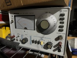
Yeah, fox and hound, that's what I have.It sounds like you are referring to one of those fox/hound type of electrical testers... they are for a different purpose; testing electrical house wires which could be 100's of feet long. It can't be use in electronic circuits where breaks could be millimeters apart. Furthermore, it's not of any use in our electronic circuits because those have no way to precisely attenuate the signal, whatever that signal may be. I can't give any "modern" generator recommendations, most instruments like these were designed for classic audio repair and so they are of the same era. Here is an example of what I use. Leader makes audio signal generators and they also make these audio "testers". The audio signal generator is probably a little cheaper and simpler which is all you need. If you look closely at the tester, you will see orders of possible attenuation, as well as adjustable tone frequency. The large knob is graduated from 1 to 10, and the buttons next to it allows you to select x10 all the way to x100k. That means if the knob is set to 1 and the x10 button is pushed, it will output 10Hz. If the knob is set to 10, and the x100k button is selected, it will output 1mHZ.
It would be nice to set the tone to 300Hz or 1kHz for this tone can be heard from the speaker if probed right there. Anything higher could sound annoying to the ear, or if higher than like 10kHz, probably isn't even audible. Knowing the frequency of the injected signal also allows you to confirm the signal via an oscilloscope if you are in a shop and don't want to torment everyone else with a siren. Then as you work your way back, you will want (need to actually) adjust the signal strength. For example, you would expect a signal to weaken if it traverses a resistor. The audio signal injected would need to be much higher directly at the speaker (and aft amp) than if injected right at the amp chip input pin because a properly working power amp would amplify the signal significantly. Typically, the further back you inject, the more attenuated the signal would need to be because there will be several layers of buffer amps, preamps, etc. On some service manuals, in addition to a block diagram, they often include a level chart. This shows how a graph of how the audio signal is amplified and attenuated as it traverses from input to output. It will actually chart how many dB the signal grows or shrinks as it goes through the system. This is an excellent guide because if the graph shows that (for example) a signal increases by 20dB after a certain transistor amp, you should be able to attenuate the audio signal the same amount to the circuit injected before the transistor and get the same audio output level heard at the speakers compared to if the signal was injected after that transistor.
Going back to which audio signal generator..... there are tons available. I would recommend you get one similar to the Leader one here. Ok, I understand they aren't something cheap like $20 or $30, like many cheap from china stuff are, but trust me, if it doesn't have adjustable tone, or a comprehensive attenuation feature, it won't be that useful. Also, I would stay away from the really old tube ones. Those could have high voltages, and it's common for those to leak alot of current, especially if the plug is reversed which is possible since those aren't usually polarized. If you can find a modern one with those features, then that's fine, but I haven't looked for one forever, and this (and a couple others I have) are working fine and probably all I'll need for the rest of my time remaining.
View attachment 58152
It's definitely way too much to use on a circuit board but it did help me locate some outlet boxes that were buried behind drywall, lol.
I'll look into them, thanks.