JVC RC-838 balance issues

caution

Member (SA)
Mar 25, 2014
2,517
349
83
Boomboxery
Of course.
If you want to hard-wire it, you need four 10K-ohm resistors, two for each channel.
Add one resistor across the pins that each line connects together. The image below shows the PCB from the bottom side.

If you want to drill a hole somewhere and hide a pot, you need a dual 20K pot with MN taper, like this one: >link<
Solder the pins that have both colors on them to the center pins of your new pot.
For the end pins, make sure that light/dark red are on left, and light/dark blue are on the right.
That ensures the left channel is lowered when you turn the pot clockwise, and the right channel is lowered when you turn it counterclockwise.


Superduper

Member (SA)
Of course.
If you want to hard-wire it, you need four 10K-ohm resistors, two for each channel.
Add one resistor across the pins that each line connects together. The image below shows the PCB from the bottom side.
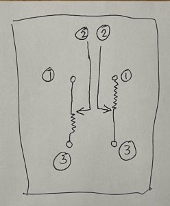
The suggestion to add a replacement pot with MN curve appears correct, but I do believe that in order to properly bypass this balance pot, you would need 2x 20k resistors, and not 4x 10k resistors. The MN curve is basically a dual pot, with one channel employing an M curve and the other channel utilizing an N curve. Essentially, either the M or N curve will provide 100% voltage at the midpoint of the pot with the rest of the travel either 100% voltage in one direction or a gradual drop to ground in the other direction with the other channel reversing that behavior. Pin 2 should always be the signal pin. The difference between the M and the N is that the end that is typically tethered to ground will switch between pins 1 and 3. In order to bypass, you will tack one end of a 20k resistor between pin 2 of each channel and the corresponding ground pin. The other pin is shorted to pin 2. If you use 4x 10k resistors, both channels will only get 50% of the signal, so both channels will be attenuated. It is a little confusing to understand when you look at the schematic of the pot since they typically show a standard variable potentiometer symbol making it look like the midpoint represents 1/2 the rated resistance, but with an MN curve, the true resistor portion is only from midpoint to one end of the travel. In the other direction, it should basically be a straight line (representing a jumper) to be technically accurate, and some diagrams show it as such.
 
Last edited:

caution

Member (SA)
Mar 25, 2014
2,517
349
83
Boomboxery
Thanks for the clarification. So in this situation, the light red/dark blue lines (tap-to-signal connections) should be shorted, and the dark red/light blue lines (tap-to-ground connections) should have a 20K resistor.
 

Superduper

Member (SA)
Here is a schematic that better illustrates how an MN pot works and why if this is a 20k pot, that you'll use 2x 20k resistors to bypass. Note how as the pot is driven one direction, that one channel maintains 100% voltage while the other channel gradually shorts to ground, and works the opposite way in the other direction. Unfortunately, irrespective of the curve/taper, schematic diagrams always just use a simple generic potentiometer symbol.

MN curve pot.jpg
 
  • Like
Reactions: Funkateer38

alcanjp

New Member
Jun 4, 2023
5
0
1
Belgium
I was just checking and I am so happy that there was some replies with great help! I will do that and get back to you for an update. I am in Europe and I have to find the part. Thank you!

PS: I am also an amateur. I do plan on using 2x 20k and I suppose that I can apply them to the schematic just above.
 
Last edited:

Superduper

Member (SA)
well, if you plan to bypass the existing sliders, bear in mind that the aforementioned is true but only if you take the existing slider out of circuit. You can't just tie into the existing solder pads with the current slider still there or else the bypass won't work properly. That is because while you think you are adding a 20k ohm resistor, the boombox thinks that resistor is actually a 10k ohm resistor due to the parallel path from the existing slider resistor. Furthermore, if the balance slider contacts (feelers) aren't completely detached and gone, they might be causing other issues internally.

you can remove the slider from circuit in a few ways:

You can cut the traces from the slider from beneath or
You can remove the existing slider completely which is probably going to be ugly
You can remove the existing slider, disassemble it and remove the internal contacts, then cut the resistor traces rendering it a dummy slider
You can remove the existing slider, trim off the leads from beneath leaving the housing legs to re-secure the slider but which renders it a dummy slider
You can desolder the slider from beneath (only the 1/2/3 leads, not the slider housing) and confirm that none of the leads are touching the pads.
And lastly, you can cut the traces from below to sever the traces, this being the last choice.

Honestly, to get to the bottom of the slider board to desolder or work on it, it is a lot of work and in my opinion, if you get that far, you might as well repair that slider properly. To remove the tone board, you will need to first desolder the entire row of solder pads that secure that board to the main board. If you try to work on that slider board with it connected to the main board, you will most likely end up damaging the traces and pads causing them to detach from the substrate.

If you are able to remove the balance slider, and you are willing to mail it to the USA, I can rebuild that slider for you for $20. Or if you wish to mail the entire board here, I can rebuild and recap the entire board for $79. You must pay shipping both ways and be forewarned that USA shipping costs are the highest in the world.
 

alcanjp

New Member
Jun 4, 2023
5
0
1
Belgium
well, if you plan to bypass the existing sliders, bear in mind that the aforementioned is true but only if you take the existing slider out of circuit. You can't just tie into the existing solder pads with the current slider still there or else the bypass won't work properly. That is because while you think you are adding a 20k ohm resistor, the boombox thinks that resistor is actually a 10k ohm resistor due to the parallel path from the existing slider resistor. Furthermore, if the balance slider contacts (feelers) aren't completely detached and gone, they might be causing other issues internally.

you can remove the slider from circuit in a few ways:

You can cut the traces from the slider from beneath or
You can remove the existing slider completely which is probably going to be ugly
You can remove the existing slider, disassemble it and remove the internal contacts, then cut the resistor traces rendering it a dummy slider
You can remove the existing slider, trim off the leads from beneath leaving the housing legs to re-secure the slider but which renders it a dummy slider
You can desolder the slider from beneath (only the 1/2/3 leads, not the slider housing) and confirm that none of the leads are touching the pads.
And lastly, you can cut the traces from below to sever the traces, this being the last choice.

Honestly, to get to the bottom of the slider board to desolder or work on it, it is a lot of work and in my opinion, if you get that far, you might as well repair that slider properly. To remove the tone board, you will need to first desolder the entire row of solder pads that secure that board to the main board. If you try to work on that slider board with it connected to the main board, you will most likely end up damaging the traces and pads causing them to detach from the substrate.

If you are able to remove the balance slider, and you are willing to mail it to the USA, I can rebuild that slider for you for $20. Or if you wish to mail the entire board here, I can rebuild and recap the entire board for $79. You must pay shipping both ways and be forewarned that USA shipping costs are the highest in the world.
Hello,


Thank you for your reply. I will consider the last option. I am not very experienced in this subject, but I am learning as I go along. Yes, shipping is now a costly issue, and sending from here is also going to be expensive, especially if I want tracking. However, this option is the wisest one for me.
 

alcanjp

New Member
Jun 4, 2023
5
0
1
Belgium
well, if you plan to bypass the existing sliders, bear in mind that the aforementioned is true but only if you take the existing slider out of circuit. You can't just tie into the existing solder pads with the current slider still there or else the bypass won't work properly. That is because while you think you are adding a 20k ohm resistor, the boombox thinks that resistor is actually a 10k ohm resistor due to the parallel path from the existing slider resistor. Furthermore, if the balance slider contacts (feelers) aren't completely detached and gone, they might be causing other issues internally.

you can remove the slider from circuit in a few ways:

You can cut the traces from the slider from beneath or
You can remove the existing slider completely which is probably going to be ugly
You can remove the existing slider, disassemble it and remove the internal contacts, then cut the resistor traces rendering it a dummy slider
You can remove the existing slider, trim off the leads from beneath leaving the housing legs to re-secure the slider but which renders it a dummy slider
You can desolder the slider from beneath (only the 1/2/3 leads, not the slider housing) and confirm that none of the leads are touching the pads.
And lastly, you can cut the traces from below to sever the traces, this being the last choice.

Honestly, to get to the bottom of the slider board to desolder or work on it, it is a lot of work and in my opinion, if you get that far, you might as well repair that slider properly. To remove the tone board, you will need to first desolder the entire row of solder pads that secure that board to the main board. If you try to work on that slider board with it connected to the main board, you will most likely end up damaging the traces and pads causing them to detach from the substrate.

If you are able to remove the balance slider, and you are willing to mail it to the USA, I can rebuild that slider for you for $20. Or if you wish to mail the entire board here, I can rebuild and recap the entire board for $79. You must pay shipping both ways and be forewarned that USA shipping costs are the highest in the world.
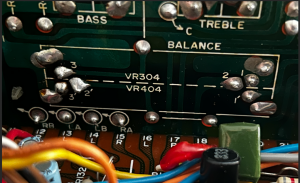
Hello,

Can I still send you the board?

Regards,
 

Cpl-Chronic

Member (SA)
May 14, 2012
2,033
39
48
Windsor, Ontario, CANADA
well, if you plan to bypass the existing sliders, bear in mind that the aforementioned is true but only if you take the existing slider out of circuit. You can't just tie into the existing solder pads with the current slider still there or else the bypass won't work properly. That is because while you think you are adding a 20k ohm resistor, the boombox thinks that resistor is actually a 10k ohm resistor due to the parallel path from the existing slider resistor. Furthermore, if the balance slider contacts (feelers) aren't completely detached and gone, they might be causing other issues internally.

you can remove the slider from circuit in a few ways:

You can cut the traces from the slider from beneath or
You can remove the existing slider completely which is probably going to be ugly
You can remove the existing slider, disassemble it and remove the internal contacts, then cut the resistor traces rendering it a dummy slider
You can remove the existing slider, trim off the leads from beneath leaving the housing legs to re-secure the slider but which renders it a dummy slider
You can desolder the slider from beneath (only the 1/2/3 leads, not the slider housing) and confirm that none of the leads are touching the pads.
And lastly, you can cut the traces from below to sever the traces, this being the last choice.

Honestly, to get to the bottom of the slider board to desolder or work on it, it is a lot of work and in my opinion, if you get that far, you might as well repair that slider properly. To remove the tone board, you will need to first desolder the entire row of solder pads that secure that board to the main board. If you try to work on that slider board with it connected to the main board, you will most likely end up damaging the traces and pads causing them to detach from the substrate.

If you are able to remove the balance slider, and you are willing to mail it to the USA, I can rebuild that slider for you for $20. Or if you wish to mail the entire board here, I can rebuild and recap the entire board for $79. You must pay shipping both ways and be forewarned that USA shipping costs are the highest in the world.
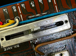
If you are able to desolder the slider board from the mainboard, sending it to Norm for a rebuild is your best bang for buck & he can restore them to new like operation, including re-capping, regreasing etc. I just had him do mine & it works like NEW!!! Love him to death for his work. Soooo cheap considering what he does for you & his time to ship etc.