JVC PC-55 - dead screen hassle , then replacement

H3NK3L

Member (SA)
Dec 17, 2020
159
121
43
France
IMG_20230409_120016.jpg

IMG_20230409_144158.jpg

IMG_20230409_144200.jpg

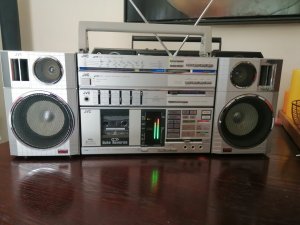
JVC PC-55 came with a dead screen (nothing unusual)...took 4 afternoons to try the "Russian method" on it (epoxy on the glass then solder wires one by one)...this worked fine..for a while...until it didnt and dead segments showed up again...went for a different epoxy...long story short : epox+soldered wires = not THE solution).

Taking a look at the schematics though I noticed "led lighting pins" on the microprocessor...one oscilloscope later : these pins actually CAN drive leds, 7.6V, square shape wave... only backdraw : the pauze, rec, direction, FF and REW led lighting pin seem to drive something else on the little LCD-pcb next to the white lightbox that holds the screen...so those are useless for my intent.

However.... led 1 2 and 3 CAN be driven directly (with a resistor ofcourse), and MS (music scan) led as well...

So after a lot of measuring, calculating, testing, printing new "screen", fitting things in (like white obscured plastic to make tiny boxes)....
after adding a 4.50 dollar 12v vu-meter 100mA ,the original lamps are 12v 200 mA so nice to use that feed for the meter (chinese, but small enough to fit into the white lightbox), putting it on the "rec out" to use that as line in to maintain the original funvtionality (meaning rec level sliders right and left work with it)....

We now have :

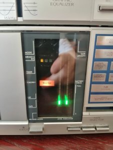
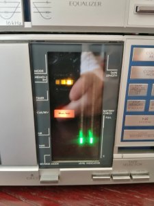
after adding 3 yellow and one orange led

a modified PC-55, with working VU-meters, 3 yellow leds indicating the play direction, indicating FF and REW (by blinking in the right direction and order but faster), indicating the Music Search Direction (by blinking twice and in the right direction) and one orange led to indicate Music Scan is active.

It s in no way up to the standards of the original lcd screen....but it s still bettr than the printed screen I put in priorly...

Nothing has been harmed during the process, original glass is in there, original lightbox is still as it should be.

PS : leds are way less violent in real life.... 1. they have a filter in front (a laser printed printed "screen" (overhead sheet) oover them and 2. they have the tainted original glass lcd in front of them.
 

Attachments

  • Like
Reactions: AE_Stereo

Brutus442

Member (SA)
Jan 7, 2012
1,297
433
83
Toronto, Canada
I have to admit to not being electrically savvy enough to understand all of what you've done but the PC-55 display looks KICK ASS!
I wish JVC adopted the black background, high contrast LED setup like you've got!
 
  • Like
Reactions: H3NK3L

H3NK3L

Member (SA)
Dec 17, 2020
159
121
43
France
Thank you!

To be honest.. The blackish background was a (happy!) coincidence... I printed a grey blueish plastic transparent sheet.. But the original lcd glass (tainted) makes it blackish.

Electrically :
The original display consists of a glass lcd panel (+a sheet of polarised plastic), which is fixed in a white box that has 2 lamps in it.
Those lamps ate 12V DC 200mA each.
So I used that 12V to power a 12V 100mA led level indicator (works on line in.. Or in this case rec out).

The microprocessor chip has a few pins on it that were in tented to drive leds... So I used those pins to drive leds (instead of the original use where they are connected to the driver for the lcd display).

But that may be a bit too technical.... What matters is the result. It s not a replacement by any means for those dying or dead lcd panels... But personally prefer having something in there than a dead screen, back-lit as it may be.
 
  • Like
Reactions: Brutus442

H3NK3L

Member (SA)
Dec 17, 2020
159
121
43
France
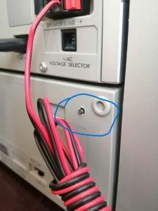
I used this thing of eBay, the "DIY" version, basically one needs only needs to solder the 2 led bars and the 5 pin connector, comes without any explanation but it's pretty straightforward, the 5 input pins have an indication of who s who on printed on the pcb, however there is no indication of the direction for the led bars, but I tried to just put one in and turn it on to see how they went in. There is a tiny button on the backside to change display mode... Basically it either goes from top to bottom - center outwards - only 2 top leds... And each of these 3 has 3 "peak hold" settings (no hold, peak hold, peak hold with peak led sliding upwards when it goes off). It does keep it's setting memorised, but I soldered 2 wires to put a 2nd button in parallel on it and placed it on the back cover of the deck.
 

Attachments

Last edited:

Wes125

Member (SA)
Aug 9, 2021
187
84
28
Uk
thats a brilliant job. id leave the led's in there as they will last for years. ive never liked lcd screens on hifi. they always fade or bits go dimmer
 
  • Like
Reactions: H3NK3L

H3NK3L

Member (SA)
Dec 17, 2020
159
121
43
France
I have noticed that it is very difficult to capture red color LED as we see it.
Even playing with exposure/ISO/white balances in manual mode does not give a proper picture.
Reality is : kindof a dark green + 80s PC-screen amber + "normal" led red
(due to the polarised original plastic screen + tainted lcd-panel)
Shiny aluminum - basic grey boombox color - metallic sourroundings seem to make it even more difficult to get them decently and realistically - sometimes putting a spotlight on them helps a bit.

If anyone has any tip or trick for photographing/filming leds ....
 

H3NK3L

Member (SA)
Dec 17, 2020
159
121
43
France
Fantastic "retro-mod" If the 55 was made today I'm sure it would have a great LCD display like that
Totslly agree, if they did a remake of it...with an oled or even led-panel that would probably be an amazing device with a lasting display.

IMG_20230423_105851.jpg

IMG_20230423_110301.jpg

The "mode selector " switch for the VU-meter (put it on parallel with the one on the (tiny) vu-meter pcb and installed it on the back of the deck. VU-meter has a few "modes" : "normal (from bottom to top), "center" (from center outwards up and down) , "modern" only lights up the 3 highest digits. And each mode then has a "peak hold" mode : off (no peak hold) , on up (peak sliding upwards after approx1 second), on down (peak digit"falling" down), normal peak (the normal 80s style :peak hold, with peak just turning off).

I would have liked putting in some more info, such as Dolby (off/on/c/d), reverse mode and such but thats beyond my capabilities because the signals for those indications are being treated by the lcd-display driver and interfering with any of its inputs messes everything up - for instance : using the "rec led lighting" pin on the micrcoprocessor for a led switches off the recording signal, using the "REVMODE led lighting" pin on the microprocessor turns of the "Reverse mode" button ,... and so on. I think someone with more knowledge (and courage and time) could manage to put in some kind of other sceen. the "bad boy" in this whole thing seems to be the pcb that drives the LCD panel (the pcb thats paraellel to the lcd-box and has all those wiring going in and out)...for which I couldnt find ANY documentation of whats on it/in it .

 
Last edited: