Crown CSC-350

H3NK3L

Member (SA)
Dec 17, 2020
159
121
43
France
I ve been restoring a Crown CSC350... But when reassembling it, putting in the long metal thing that goes from the tapedeck to the rec switch, I somehow messed thing up, and probably didn't quite put it in the same position it was supposed to be in.

Everything worked fine before but first time I hit REC, no more tuner dolby or sound... Taking a closer look at it I can only imagine the metal bar connecting tapedeck to rec switch touched the power pins next to it...

So everything powers up, but no radio or sound or dolby.

If anyone can give me any leads on this, I would highly appreciate it.

For now I m presuming (but blindly) I grounded some power pins... And either messed up the power I C s. But any advice welcome on how to tackle and find the cause.
 

floyd

Member (SA)
Jan 9, 2022
1,059
788
113
55
Maryland usa
Unless you are sure you shorted something out . it may just be the record bar is not lined up right and it's not letting the audio signals pass through like they should. I had this happen before when I hooked the connecting rod to the wrong slot on the record bar.
 
  • Like
Reactions: BoomboxLover48

BoomboxLover48

Member (SA)
Dec 3, 2010
5,763
275
83
Chicago, IL
Unless you are sure you shorted something out . it may just be the record bar is not lined up right and it's not letting the audio signals pass through like they should. I had this happen before when I hooked the connecting rod to the wrong slot on the record bar.
Floyd explained it well. Clean the record switch well and put the record bar lined up.
Good luck!
 

H3NK3L

Member (SA)
Dec 17, 2020
159
121
43
France
Unless you are sure you shorted something out . it may just be the record bar is not lined up right and it's not letting the audio signals pass through like they should. I had this happen before when I hooked the connecting rod to the wrong slot on the record bar.
Thank you for that , but afraid thats not it...unless i broke something in it... Thouroughly cleaned and switched (manually) a hell of a lot of times, even during manually switching (pullint it out) nothing happens. I cant feel any sideway movement in it, it pretty much goes straight in and out, cant wiggle it.

When powered on :
- both vu meters react normal - strike out full then go back
- tape works fine, REW, ff, play, PAUZE but no signal (AMSS not working)
- no tuner
- no dolby, led not lighting up
- no line in
- no AMSS , but AMSS leds do light up
- no humming on speakers, nor on headphone : only the slight click when powered on/off but barely noticeable


So I think,, abouy 95pct sure...I shorted something....somehow...and the only way that could have happened to all logic would be that metal connector touching those voltage pins. No smoke or anything..unfortunately (makes things easier to figure out lol). Just hit REC to see if I connected it correctly, REC light came on and all the rest went dead (except for the tape deck ), no sound no radio no nothing. Which makes me think at 95pct certainty that the rec bar metal thing touched one or more of those pins. My gut feeling kindof says : something isnt getting power

(5pct : I ll try to remove the rec bar and clean it when its out, there seem to be no cracks in any soldering on it, but a reflow + out of the boombox cleaning may do the trick)

My first guess was : hell you pulled on a wire and it came loose so something isnt getting powered, but all is still where it should be, soldering is fine, no loose wires.
Second guess : you messed up the rec bar, somehow pulled too hard on it, ... but...I dont think I did, I was quite careful to only put on the hook on the rec bar as final manoeuvre and did so without pulling on it, only pulled on the huge metal connecting thing.

I dont have a service manual :( 
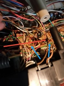
All pins seem to have voltages (8,47 V 11,96V and such, which to me seens normal), except for the pink ones, no idea what those do or or supposed to feed. So before I go changing power regulators and such....I prefere asking the more wise :)


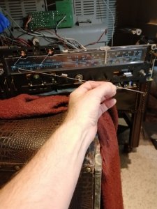
here are the pictures of the huuuuuuuuge metal thing that goes all the way from the left of the tapedeck to the rec bar


RED : path of the metal thing going from tape deck to rec bar
BLUE : left : where all those pins are - right : the rec bar hook (not very visible but its the square white thing)


IMG_20231129_172218_edit_1312520247852850.jpg


IMG_20231129_172239.jpg
 
Last edited:

H3NK3L

Member (SA)
Dec 17, 2020
159
121
43
France
Unless you are sure you shorted something out . it may just be the record bar is not lined up right and it's not letting the audio signals pass through like they should. I had this happen before when I hooked the connecting rod to the wrong slot on the record bar.
The rod can only connect to 1 thing on the rec bar on mine (the square part sticking out, where it was connected before I took it out to service the tapedeck),
however there are 3 position on the tapedeck side (3 holes one can hook the thing into). I originally took it out of the 2nd (middle) hole... I took it out of the tapedeckfirst (only had tu pull it up for that, while on the rec bar side it has a different shape - on the picture in my previous post I m holding it in the wrong direction)

I flooded the rec bar again with contact cleaner, moved it in and out quite a lot of times (Stopped counting at 25)...hooked the rod into it and into the tapedeck end...and now no matter what "hole" I pick on the tapedeck...tapedeck stays stuck in REC (button doesnt release when hitting STOP)..and ofcourse the rec bar stays in REC mode. Howver when I unhook it.... tapedeck snaps out of REC whenever I hit STOP.

Going to follow up on the REC bar lead you gave me !! something seems off there indeed...dont know what but since the tapedeck rec thing pulls slightly harder on the connecting rod when coming out of REC (on tapedeck), something is not letting it do that...so I m presuming its the REC bar thing that should probably be able to move ever so slightly more out before the spring on it puts it back in play mode ? I tried manually to keep the rec switch from getting back in completely but that didnt change anything.

Thanks for the tip ! and I ll give that rec bar a very very very good and close look tomorrow and let you know :)
 

H3NK3L

Member (SA)
Dec 17, 2020
159
121
43
France
Follow up:

Rec bar seems to be fine and work as it should (I m presuming, dont have the service manual but connection seems to be made / undone when switching it)

So I m still thinking : that metal rod touched one or more of the 3 voltage pins, dont know if my logic is solid : If it touched one or more of those pins...the rod being connected to the metal part of the tape deck, that tapedeck having all its metal parts connected to GROUND... it must have put those 12V - 9V pins to ground...
My electronics education is a bit far in the past but if I m following logic : that would mean ground has received 12 V / 9V... so, please correct me if I m wrong...the next step would be :

- verify the voltage on the pins
- follow the path of that tape-deck GROUND...
- check the ICs (which are usually the "weakest" links since they dont really appreciate receiving voltages on their ground pin)

?


Would that be a logical next step or do any of the more wise people on here have a more decent idea ??


PS : @Reli , definately a good tuner lighting system....but with some flaws in my opinion, the 90 degree angle +45 degree grinding on the front isnt all that efficient and the black rubber holding the lights, with only a small slit on it to guide it isnt very efficient either.... personally I prefer the Sanyo way : a hole INSIDE the transparent printed perspex/acrylic plate with a "mirror" cap over it, keeping most of the light to disperse inside the perspex/acrylic plate. But I do agree on the looks of it, this kind of blueish on black is very classy ! When/if I get to find the problem and solve it, I ll give it some leds instead of the soldered bulbs, going for warm white / incandescent immitatiom - or white white depending on how it looks - but keeping the leds invisible, and lighting the perspex/acrylic inside not from the outside.
 

floyd

Member (SA)
Jan 9, 2022
1,059
788
113
55
Maryland usa
i hope this works out for you Sir, lovely looking boomer this one indeed :thumbsup:
If you have no sound at all on any source then it could be the ic chip or the pre amp board. If the vu meters work normally then the pre amp section is ok so it might be the amp ic
.
 

Radio raheem

Member (SA)
May 13, 2009
4,971
922
113
uk
If you have no sound at all on any source then it could be the ic chip or the pre amp board. If the vu meters work normally then the pre amp section is ok so it might be the amp ic
.
i had a sony fh like that lad, it was indeed the ic :yes:
 

floyd

Member (SA)
Jan 9, 2022
1,059
788
113
55
Maryland usa
Follow up:

Rec bar seems to be fine and work as it should (I m presuming, dont have the service manual but connection seems to be made / undone when switching it)

So I m still thinking : that metal rod touched one or more of the 3 voltage pins, dont know if my logic is solid : If it touched one or more of those pins...the rod being connected to the metal part of the tape deck, that tapedeck having all its metal parts connected to GROUND... it must have put those 12V - 9V pins to ground...
My electronics education is a bit far in the past but if I m following logic : that would mean ground has received 12 V / 9V... so, please correct me if I m wrong...the next step would be :

- verify the voltage on the pins
- follow the path of that tape-deck GROUND...
- check the ICs (which are usually the "weakest" links since they dont really appreciate receiving voltages on their ground pin)

?


Would that be a logical next step or do any of the more wise people on here have a more decent idea ??


PS : @Reli , definately a good tuner lighting system....but with some flaws in my opinion, the 90 degree angle +45 degree grinding on the front isnt all that efficient and the black rubber holding the lights, with only a small slit on it to guide it isnt very efficient either.... personally I prefer the Sanyo way : a hole INSIDE the transparent printed perspex/acrylic plate with a "mirror" cap over it, keeping most of the light to disperse inside the perspex/acrylic plate. But I do agree on the looks of it, this kind of blueish on black is very classy ! When/if I get to find the problem and solve it, I ll give it some leds instead of the soldered bulbs, going for warm white / incandescent immitatiom - or white white depending on how it looks - but keeping the leds invisible, and lighting the perspex/acrylic inside not from the outside.
One thing I would do in the future is insulate that connecting rod to isolate it from touching anything all you really have to do is just wrap it once with electrical tape or anything just to isolated from other parts in case something happens.
 
  • Like
Reactions: H3NK3L

H3NK3L

Member (SA)
Dec 17, 2020
159
121
43
France
One thing I would do in the future is insulate that connecting rod to isolate it from touching anything all you really have to do is just wrap it once with electrical tape or anything just to isolated from other parts in case something happens.
one step ahead on that...I covered it with theremorectractable tubing over its length, leaving only its hooks and spring open. Just felt and feel a bit silly/stupid/... cause I took good care to unplug the whole thing to put it back in - just never concidered it would move a bit and could this kind of thing.
 

H3NK3L

Member (SA)
Dec 17, 2020
159
121
43
France
i had a sony fh like that lad, it was indeed the ic :yes:
Thanks for that !
what IC in particular should I be looking at ? (there a quite a few.... ) Was thinking to start at the beginning - again \i have no service manual and am kindof working from common sense - like check out the powerboard that has 2 huge voltage ICs, rated 30 watts each...and then a few lower power regulator ICs that handle the different voltag rails.

There is no pre amp board on this, it s jus a huuuuuuuge board holding everything (tape control, preamp, tuner, dolby,...) but powerboard and amp board. ishThats kindof what makes me freak out a bit... I can recognize the tuner IC, preamps, dolby chips, stereo demodulator IC and such but there doenst seem to be any logic to their locations - it s just one huuuuuuge board with loads of stuff on it, with probably some kind of logic to whats where but the whole this is ONE board, most likely having only ONE ground path...which probably received (thanks to me) 9V or 12V or both ...

Currently restoring a Sanyo M-x920 for a friend (trying to get it ready for him before xmas holidays), he s the one who GAVE me the crown (which then was working with a lot of defects but basics working). X-920 with its tapedeck being a mess and only having mono and one channel....is almost peanuts compared to te crown I messed up. Got 2 channels back, stereo and wide - dolby back to work and even the tapedeck is nearly fully working again.

Getting bach to the crown when I finish his Sanyo.
 

floyd

Member (SA)
Jan 9, 2022
1,059
788
113
55
Maryland usa
Thanks for that !
what IC in particular should I be looking at ? (there a quite a few.... ) Was thinking to start at the beginning - again \i have no service manual and am kindof working from common sense - like check out the powerboard that has 2 huge voltage ICs, rated 30 watts each...and then a few lower power regulator ICs that handle the different voltag rails.

There is no pre amp board on this, it s jus a huuuuuuuge board holding everything (tape control, preamp, tuner, dolby,...) but powerboard and amp board. ishThats kindof what makes me freak out a bit... I can recognize the tuner IC, preamps, dolby chips, stereo demodulator IC and such but there doenst seem to be any logic to their locations - it s just one huuuuuuge board with loads of stuff on it, with probably some kind of logic to whats where but the whole this is ONE board, most likely having only ONE ground path...which probably received (thanks to me) 9V or 12V or both ...

Currently restoring a Sanyo M-x920 for a friend (trying to get it ready for him before xmas holidays), he s the one who GAVE me the crown (which then was working with a lot of defects but basics working). X-920 with its tapedeck being a mess and only having mono and one channel....is almost peanuts compared to te crown I messed up. Got 2 channels back, stereo and wide - dolby back to work and even the tapedeck is nearly fully working again.

Getting bach to the crown when I finish his Sanyo.
Wherever the amplifier ICS are there should be an aluminum heat sink of some type
 

Radio raheem

Member (SA)
May 13, 2009
4,971
922
113
uk
Thanks for that !
what IC in particular should I be looking at ? (there a quite a few.... ) Was thinking to start at the beginning - again \i have no service manual and am kindof working from common sense - like check out the powerboard that has 2 huge voltage ICs, rated 30 watts each...and then a few lower power regulator ICs that handle the different voltag rails.

There is no pre amp board on this, it s jus a huuuuuuuge board holding everything (tape control, preamp, tuner, dolby,...) but powerboard and amp board. ishThats kindof what makes me freak out a bit... I can recognize the tuner IC, preamps, dolby chips, stereo demodulator IC and such but there doenst seem to be any logic to their locations - it s just one huuuuuuge board with loads of stuff on it, with probably some kind of logic to whats where but the whole this is ONE board, most likely having only ONE ground path...which probably received (thanks to me) 9V or 12V or both ...

Currently restoring a Sanyo M-x920 for a friend (trying to get it ready for him before xmas holidays), he s the one who GAVE me the crown (which then was working with a lot of defects but basics working). X-920 with its tapedeck being a mess and only having mono and one channel....is almost peanuts compared to te crown I messed up. Got 2 channels back, stereo and wide - dolby back to work and even the tapedeck is nearly fully working again.

Getting bach to the crown when I finish his Sanyo.
it could also be something as simple as a blown resistor my friend to be honest i wouldn't know as i have a guy that does all that for me........do you have access to a service manual/////you would need someone's help like good ol superduper
 
Last edited:
  • Like
Reactions: H3NK3L

H3NK3L

Member (SA)
Dec 17, 2020
159
121
43
France
it could also be something as simple as a blown resistor my friend to be honest i wouldn't know as i have a guy that does all that for me........do you have access to a service manual/////you would need someone's help like good ol superduper
I m going to get myself the service manual, because you are right as far as I know so far... It could be anything... From a blown diode to a "fuse resistor" to something more simple... Like the REC bar could have been...

Thanks for the help so far!

I think if I can't find it for free I ll go see superdupers site for the manual, before bothering him. I think he s. Kindof the wise man on here. The Oracle for the likes of us lol
 
  • Like
Reactions: Radio raheem

H3NK3L

Member (SA)
Dec 17, 2020
159
121
43
France
Wherever the amplifier ICS are there should be an aluminum heat sink of some type
They are on a separate board, but I don't think it's an amp problem.... As far as I know the amp chip doesn't supply power to the tuner... Tuner nor any other input turn on. If the were the amp I think the tuner would still turn on. Anyways I ll leave it for now and get back to it in a week or 2, and do the wiser thing and get my hands on a service manual before going in blind(folded)... Thanks for the tips and assistance so far!