Sanyo 9935k Restoration and Line In

Status
Not open for further replies.

BlackMoses

Member (SA)
Mar 14, 2011
48
1
0
36
San Diego, CA
Hey guys and gals!

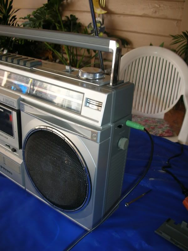
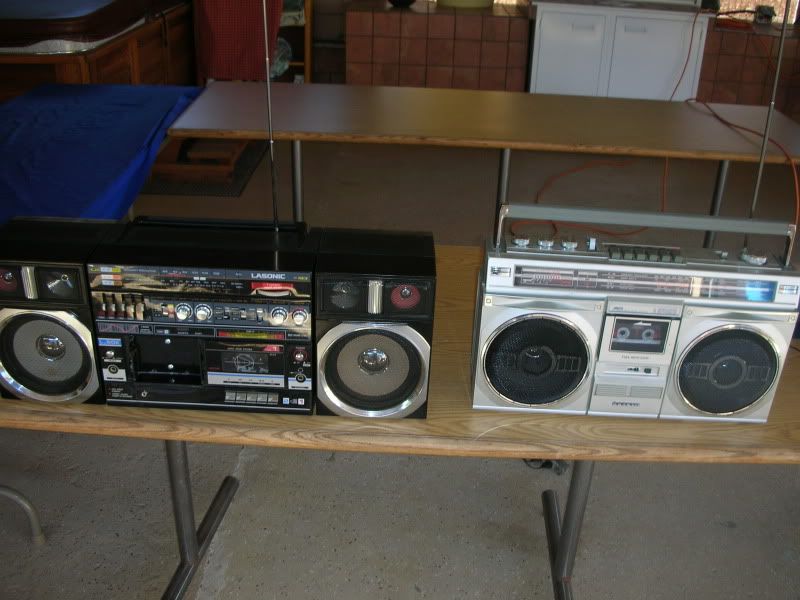
This is my first post but I've been around the site for a little reading and learning about boomboxes. Currently I've got a Lasonic L-30K and my recent addition to the family is a Sanyo 9935. I've seen a few people talk about their 9935, especially Old School Scott's black one, WHICH LOOKS AWESOME, so I'm hoping a few of you guys can give me some pointers.

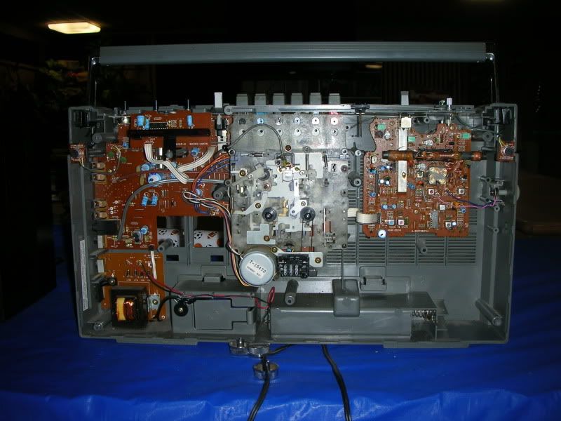
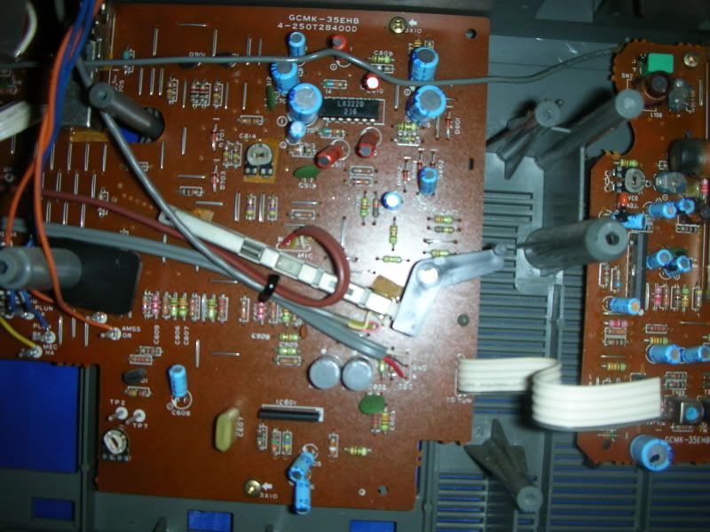
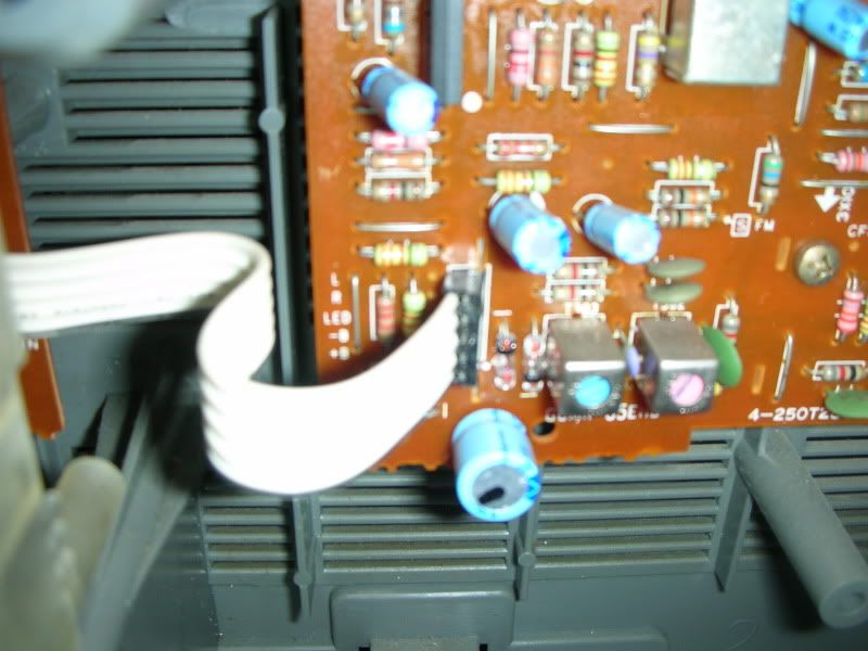
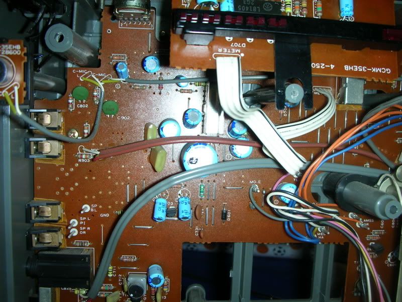
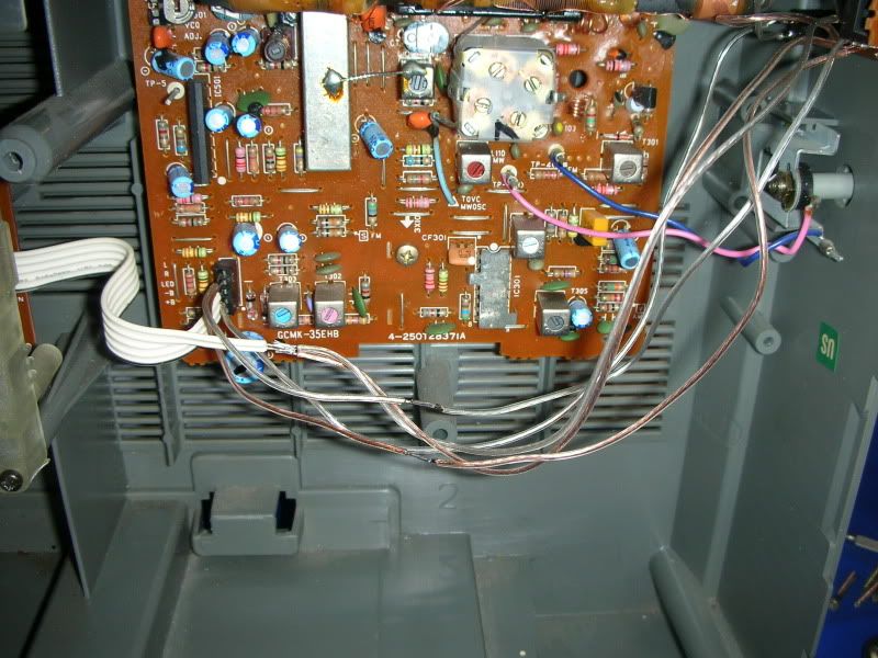
Anyways I just got the box today and I've been in the process of cleaning it up (removing paint splatter, repainting the grills, cleaning etc.) but my next step is to add a line in to the box. SO, that being said I did some poking around on the inside and found that the tuner is separate from the main board, and that there is ribbon cable going over. The cable is separated into L, R, LED, B- and B+. After playing with the leads a little bit from a 3.5 mm stereo jack hooked into my iPod, I'm able to get sound when I plug into the L and R wires after disconnecting the tuner, but there's essentially no bass. When I hook the leads to either the L or R and one to the B +/- I get a fuller sound but it's distorted.

So anyone have any ideas about where I could wire in a 3.5 mm jack and then put it on a switch so that way I don't loose any functionality? Pictures are attached!

Thanks in advance.

Bryan


baddboybill

Member (SA)
Jul 14, 2009
11,092
89
48
55
Hudson Florida
:hi: :hi: to site. Honestly that bbx looks pretty nice on inside, why would you want to mess it up :huh: :-O this is all just my opinion but why don't you get a bbx with line in already or get a beater box to work on so then this way if something don't work then it's not a real big loss :hmmm:
 

jaetee

Member (SA)
May 5, 2009
2,042
8
38
Florida's West Coast
I kind of gotta agree with badboybill on that one...

9935 is a decent (but very basic) box that plays tapes pretty good... Rather than mess with killing the tuner for sake of modding a line-in, how about an inexpensive FM converter (you can listen to same thing on both boxes simultaneously) or maybe one of those cheapo MP3 players that looks like a tape and plays mp3's thourh the cassette head.

There are so many boxes out there in that size class with switchable line-in. Consider that as a good rationalization tool for buying another. :) I recommend you pick up something like a Panasonic RX-5150 or something in that range (5050 or 5085). Those are plentiful, sound good and can be had for very reasonable $$$.

Good luck, whichever way you decide to go!
 

BlackMoses

Member (SA)
Mar 14, 2011
48
1
0
36
San Diego, CA
Thanks for the replies! My intention is definitely to keep this thing as original as possible and by adding some sort of line in I don't want to sacrifice any of the original features. Really the only modification would be putting some sort of switch and 3.5 mm jack on the side of the box, very minimal in terms of changing anything.

That being said, if there's no slick way to put this in there I'm not opposed to just leaving it alone.

Pictures of the entire box will follow soon!
 

BlackMoses

Member (SA)
Mar 14, 2011
48
1
0
36
San Diego, CA
Well I seem to have found a way to make this work, obviously I have my left and right channel going into L and R, however my negative leads connected to B- seem to work pretty well. Granted at quarter volume I'm getting some speaker distortion, but I think that's to be expected with these cheaper paper drivers.

I found a schematic here, and I'm pretty sure I have the same integrated controller LA336 as the one in this schematic, so I'm probably dealing with something similar. Based on that assumption, B -/+ seems to be a anti feedback of sorts and a mono amp? What do you guys think...I don't think I'm hurting anything with this setup.
 

Superduper

Member (SA)
I think that if you don't quit experimenting with hooking up your equipment to various wiring by guessing, you could damage your ipod, your boombox or both for good. Clearly you don't understand enough about electronics to know how signals work and travel.

First off, the bat +/- are not feedback circuits. They are the power rails that supplies current to your tuner. Hooking up the L/R is correct, as long as you know how to extract the proper signals from your 3.5mm jack. However, your ipod has a 3-pin output jack. The third connection is the negative that is shared between the L and R. In other words, each channel requires L+/L- and R+/R-. The Bat - can be used as a ground for your application. However, when you initially connected your ipod to the +B connection, just keep in mind that you were injecting FULL boombox battery voltage into your ipod and into the boombox preamp. In the reverse direction! Whenever current leaves a power source, it MUST find a path back to complete the circuit. The reason you still heard audio is because the positive power rail was being modulated by the ipod but the distortion was fully expected. Ipods work at very low voltages and you were injecting probably somewhere between 9 and 14 volts into it, when NO current should've have been injected. Of course after the signal was injected into the ipod, it goes back into the boombox preamp, again in the reverse direction. Nobody would hook up the battery leads to your car backwards and expect it to last, much less work correct, right? Connecting the last wire to ground (B-) is correct, again, as long as you've properly extracted the +L and +R signals and not mixed them up or connecting them backwards or pairing them up wrong. If you are not hearing much bass, it's probably because your ipod was not turned up all the way. Headphone-in signal voltages are usually lower a little lower than standard line-in signal levels. With a small injected signal, the sound will not be very full.

So in response to your comment that you don't think you are harming anything........... all I can say is stay tuned, if you keep it up.
 

Chordeater

Member (SA)
Feb 8, 2011
73
0
0
Oviedo, Spain
Hi,

maybe I missunderstood something, but why don't you use a DIN-RCA adapter? I use it with my M9935 to feed it with my iPod and works fine ...


Cheers.
 

BlackMoses

Member (SA)
Mar 14, 2011
48
1
0
36
San Diego, CA
Thanks for the responses. I wasn't sure about the B connectors on the board but being the battery connection for the tuner makes a lot of sense. I have the common negative lead from the 3.5 cable going into the negative battery like you had suggested, I merely experimented with hooking up to the B+ lead and I can assure you nothing was damaged. Everything is wired in there right now and I have a switch that allows me to go between the radio and 3.5 mm input, so I think it's all good to go. There's still some distortion but again that's at higher volumes with the VU meter near the top, so I think it's to be expected with these drivers.

I would of used a DIN however my box doesn't have one!

Thanks for the help, I'll get some pictures with how it turned out.
 

BlackMoses

Member (SA)
Mar 14, 2011
48
1
0
36
San Diego, CA
Alright picture time...I think it came out pretty well, the only thing I might go back and do is tidy the wire runs a bit, but it's fully functional and I think it looks good without really changing the original stylings of the box.


Here's the switch and 3.5 mm jack.


Outside shot.


All done!


Next to my Lasonic L-30 which is next in line for some fixing up. When I got the thing the 2nd tape deck was pretty much ripped out, so I did my best to close it up and make it original as possible, so next on the agenda is to redo what I did and incorporate a LED color organ into it. Should be cool and I'll document on here for you guys to see.


Superduper

Member (SA)
teamstress said:
I hope you insulated those spliced wires or poof!
Well since shrink tubing needs to be inserted before doing the splicing, it looks like the only way to insulate them now is to use electrical tape, which I'm not a big fan of.

Excellent job installing the switch though. How did you make such a perfect rectangular hole? That took some skillz to make it look good.

Also, perhaps I'm missing something here but it looks like from your image that you soldered the L and R signal wires together. If that is the case, and that's what it appears ... :-O :nonono: :dunce: I presume you did that because you used SPST switch instead of a DPST, (or didn't know how to rig the switch/jack to do stereo) and have now converted your STEREO boombox into a dual speaker mono-box. Or am I wrong?
 

BlackMoses

Member (SA)
Mar 14, 2011
48
1
0
36
San Diego, CA
Hey guys, I ended up putting some electrical tape on the joints just because I didn't have any shrink tube. Superduper, the picture is at a bad angle but the left and right channels are soldered into their respective inputs. As far as the switch, I believe it's a dual pole dual throw (I think, after reading on wikipedia), essentially I have the left and right from the 3.5 mm on one end, the input to the main board in the middle, and the input from the radio on the other end. Does that make sense? Each is split into L and R

The rectangular hole was actually just two drilled out holes that I took a little file and edged them out, I think it worked pretty well!


This is what I'm going to incorporate into the Lasonic... http://blog.makezine.com/archive/2010/1 ... -spon.html
 

Superduper

Member (SA)
BlackMoses said:
Superduper, the picture is at a bad angle but the left and right channels are soldered into their respective inputs. As far as the switch, I believe it's a dual pole dual throw (I think, after reading on wikipedia), essentially I have the left and right from the 3.5 mm on one end, the input to the main board in the middle, and the input from the radio on the other end. Does that make sense? Each is split into L and R

The rectangular hole was actually just two drilled out holes that I took a little file and edged them out, I think it worked pretty well!
In that case, good job! :thumbsup: Next time, use heat shrink tubing because it works much better, material is thicker, and doesn't come apart and get sticky over time. Also, try to keep the wires neater, bundled and fixed to prevent vibrations and other issues.
 

Lexedus

Member (SA)
May 24, 2011
9
0
0
Forgive the shoddy Visio, but I don't have the electronics module.
I'm going to attempt this on my box and thought I'd run this by you guys, see what you thought...
I'll post pictures of the execution when I get to work on it.


Superduper

Member (SA)
your diagram does not show the schematic for this component so there's no way for us to comment on it. Firstly, you show 5 connections to the jack but I suspect that this Radio shack jack will only have 3. Then looking at the radio shack catalog, this component does not indicate that it's a switched jack. If that is the case, if you connect in this manner, the new "line-in" will be mixed with the tuner. Finally, without a schematic, we can not know how it's internally connected.
 

Lexedus

Member (SA)
May 24, 2011
9
0
0
Superduper said:
your diagram does not show the schematic for this component so there's no way for us to comment on it. Firstly, you show 5 connections to the jack but I suspect that this Radio shack jack will only have 3. Then looking at the radio shack catalog, this component does not indicate that it's a switched jack. If that is the case, if you connect in this manner, the new "line-in" will be mixed with the tuner. Finally, without a schematic, we can not know how it's internally connected.
My bad. I tried to show that with the color coding, but here's a scan of the back of the packaging. and the jack itself.

I was afraid it would only have 3 and I'd have to wire in a switch like BlackMoses, but was happy to find this instead.


BlackMoses

Member (SA)
Mar 14, 2011
48
1
0
36
San Diego, CA
Unless I'm mistaken Lexedus, you're going to run into a problem with that setup. When you try to hook up your iPod to the 3.5mm headphone jack there and you have it switched to radio not only will you have the signal from the radio, but the iPod as well. The reason I implemented the switch was to isolate both signals completely from each other because once the boombox's function is set to radio, you're going to have a signal headed to the amp from the radio line, however if I want to listen to my iPod I need to cut off that radio signal completely and just allow for the iPod input.

Does that make sense?

Unless I'm reading the diagram wrong on your jack you have there, those connections will always be bridged together?
 

Lexedus

Member (SA)
May 24, 2011
9
0
0
NO, I guess its not apparent, but when you insert the plug into the jack, it separates the 2 from 3, 4 from 5.
That is to say, it leaves a closed circuit between the amp and the radio when the jack is open, but when you insert the plug, it opens the connections to the radio.
Looking at your photos, it looks like the jack you used had only 3 posts. A ring, a tip, and a ground. This has 5 to enable the circuit to close when the jack is not in use.

In examining the diagram and the box itself, I did realize I almost made one fatal flaw!
I was about to wire it to send ipod signal to the radio rather than the amp. Whoops!

It should actually look like this.


Lexedus

Member (SA)
May 24, 2011
9
0
0
I tested it and it works.
It really makes more sense if you can see it in action. I should have posted a photo of the jack with a plug in vs. open, that way you see how the connections shift.
If it helps, the photos of the jack are on opposite sides, I didn't open it up or anything, so the connections you see in the top photo are opposite of the terminals in the photo below.
I got it all wired up so all I have to do is turn the radio on then plug in the iPod. Switches flawlessly.

Input plug

Nestled between the existing jacks

Wires routed through box. Bundled with mesh tubing fixed on ends with HST

Connections to board. Wires ends coated with solder and ground down to fit the terminals.
 
Status
Not open for further replies.