Display backlight broken on JVC Kaboom rv-nb99bk

Status
Not open for further replies.

martin

Member (SA)
Jan 16, 2011
10
0
0
Berlin, Germany
Hello Boomboxers! :-)

I just bought my first boombox from ebay, a JVC Kaboom rv-nb99bk. I know, it's not the real deal compared to the boxy boomboxes from the 80s, but I read so much about it's ability, to rock a small party standalone, that I decided to replace my crappy hifi in berlin with it. If I ever am in money, I will probably try to get a real one with better sound quality, as I hear it can't compete with my real hifi, but for the moment it serves my needs just right. :breakdance: It really is a KABOOM!

Everything seems to work perfectly and except for one scratch it looks beautiful as new. BUT there is one problem:

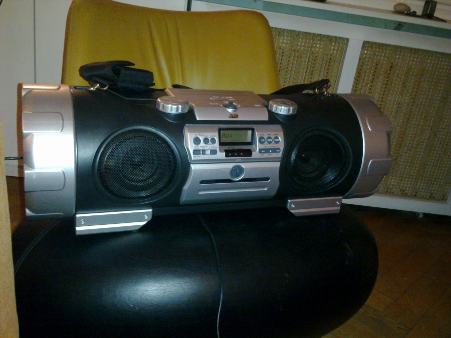
I can't get the display backlight to work. As you can see below, it clearly shows AUX and is currently singing in it's boomy voice, but there is no orange light. :sadno:


It is only a small drawback as I got a good price on this (220 euros is not too much, right?), but I would love to see what it says in the dark.

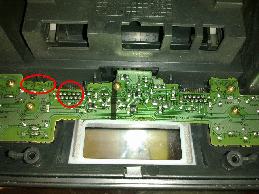
Is it possible to open this part of the box without hurting it too much? I guess, then it shouldn't be too hard to fix the LEDs.

Also, the orange light makes it look like the party animal has its own eyes and is watching while booming! :jacko:

Thanks so much in advance!

Greetings from Germany, martin
 

martin

Member (SA)
Jan 16, 2011
10
0
0
Berlin, Germany
just an FYI:

the box is open right now and I'm taking pictures, so if anyone needs some information or pics of the inside, let me know. ;-)
 

martin

Member (SA)
Jan 16, 2011
10
0
0
Berlin, Germany
as seen on the picture, there is some kind of a metal box behind the display. I'm guessing the LED is in there, but in the moment i don't really know how to get in there without destroying even more.

EDIT: Okay, this little metal box is pretty sealed. I'm guessing it's glued or there's a connector system inside. The metal Box is tightly attached to the top of the display. I guess it would be possible to get it off the circuits on it's bottom, but then I would tear the display connections apart. Also, there is a circuit in the back of the metal box, I think the LED must be exactly attached to it. So now I'm trying to find a dentists mirror to see the back of this little circuits plate, perhaps there is a cold solder joint/dry point.
If not, I don't know if it's a good idea to get that little back circuit off the metal box with a knife and careful violence... =(
Additionaly, if I want to get those circuits a bit out of there, it looks like I have to get the WHOLE circuit system out of the plastic and I'm a bit afraid of that...


martin

Member (SA)
Jan 16, 2011
10
0
0
Berlin, Germany
Wow, a real lamp inside? Thanks for the tip with teh CD player part. Something seems to be holding it inside. Not hard like a screw but soft like a spring. Do I need to completely disassemble the unit just to release the CD part? It feels like one of those band connections is holding it back.

Here are my newest finds:

First, with the dentists mirror I could see, that I can easily release the circuit from the metal box by twisting some metal from the metal box. There is a little piece of metal coming through from the inside of the circuit and it is twisted a bit to hold the circuit to the metal box.

Second, I found a solder joint, that seems to be cold. You see in the red circle there is one solder joint not "soldered". The description in the other red circle says NC, which is a "normally closed" break contact of a relais. This could be the lamp, right? Directly beneath those ten soldering joints is the connection to the other side of the box. The counterpart has ten correctly soldered soldering joints. I wonder, though, because it looks like it has no "circuit path" leading to it.

Is it safe to solder that joint? How to do it best?


Superduper

Member (SA)
Do not solder that connection. NC in this case means not connected. NC (normally closed) only refers to switches and relays, not connections.

Think twice before attempting any soldering task on these boards. These are high density double sided boards. Without top quality soldering equipment and an experienced hand, you could easily damage that board. Also, many connections are vias. That means the solder pad could make an electrical connection on both sides of the board. It may look like it's good on one side but not actually be connected. My advice -- don't mess with anything unless you are sure. The lamp is almost 99.9% burnt out so don't tinker with anything else and hope it's anything simpler (or more complicated) than that.
 

martin

Member (SA)
Jan 16, 2011
10
0
0
Berlin, Germany
to be honest I was so sure because of the soldering on the counterpart, that i already soldered it... luckily, it didn't change anything. I turned it on and everything worked like before. :blush: :angelic: but as I read your comment my hear heart sank right down into my pants... :'-( I just learned avaluable lesson...

Here is the little light emitter. It has PL1 as description and a pretty burnt wire in it. Also there is a sign besides it, that looks like wires in a bulb.

I bet I can't replace that with an LED? How do I find out what kind of new emitter to buy?
Also, the color of the emitter seems to be the color of the display, so I might change that and have a mini mod... :-)

EDIT: how about a red or green one of these? would that work?
http://www.conrad.de/ce/ProductDeta...productcode=727091&zanpid=1464364398960189440


Superduper

Member (SA)
That's the one. You can see the symbol clearly indicates that it's a panel lamp and not an LED, which would be polarity specific. You'll need to test to find out what the normal "live" voltage is. With that, you can determine what size lamp to replace with or how to calculate the required series resistor to insert into the circuit. Any color will do. Problem with LED is that they are bright but have a very focused light angle unlike incandescents which illuminates from every angle. So if you do install an LED, you may have a problem where it looks like the panel is illuminated with a laser or spotlight. One single bright spot in the center. You can alleviate that somewhat by scuffing up the surface of the LED with sandpaper or something which will help diffuse the light a bit. The plus of LED of course is that they will last a very long time compared to panel lamps which burn out all the time.
 

martin

Member (SA)
Jan 16, 2011
10
0
0
Berlin, Germany
I can do the measuring with a normal multimeter, measuring at the soldering joints of the lamp, right?

I will definitely go for a panel lamp in that case. I don't mind replacing, as I now know what to do. It might be fun to change the color from time to time when it burns out.
Red will look cool. Green could also be nice, but perhaps not so nice when trying to fall asleep to music.

I hoped, since the kaboom can be powered on 12V, a 6-12V lamp would do the job. By the way, the transformer from 230V to 12V when using normal electricity from the wall must be somewhere inside of the unit, right? Or is it running on more energy then?

Thanks for all the help, by the way! :yes:
 

Superduper

Member (SA)
I always thought the kaboom takes 10-D cells which would make it 15volts. The transformer will probably output more -- I would suspect somewhere between 18 to 21 volts. You should test the voltage with the unit connected to mains. The voltage may be regulated to a lower voltage or might not be. You need to test to be sure.
 

baddboybill

Member (SA)
Jul 14, 2009
11,091
84
48
55
Hudson Florida
Superduper said:
I always thought the kaboom takes 10-D cells which would make it 15volts. The transformer will probably output more -- I would suspect somewhere between 18 to 21 volts. You should test the voltage with the unit connected to mains. The voltage may be regulated to a lower voltage or might not be. You need to test to be sure.
:agree: :agree:
 

martin

Member (SA)
Jan 16, 2011
10
0
0
Berlin, Germany
Well, it takes either 230V AC from the wall or 12V DC from the adapter to the car battery or ten D cells, which can either be non-rechargeable 1.5V or rechargeable 1.2V.

I guess this just means I should go for safety and measure... ;-)

...but more on that (and hopefully cool red glowing pictures) will come next weekend, when I'm back in Berlin. :-)
 
Status
Not open for further replies.