So I’ve looked through posts on the RX5350 with zero about output for meters. I have an issue with right meter 0 reading...left works fine. FM signal strength on right works fine. Both VR for meter output work fine. Any ideas????
Panny RX5350 right side meter not working
- Thread starter baddboybill
- Start date
Be sure to grab the service manual from the library if you haven't done so already.
http://www.mediafire.com/file/xr6em725scjd3v3/Panasonic_RX-5350_Service_Manual.pdf/file
http://www.mediafire.com/file/xr6em725scjd3v3/Panasonic_RX-5350_Service_Manual.pdf/file
I did Bobby thank you 😊Fatdog said:Be sure to grab the service manual from the library if you haven't done so already.
http://www.mediafire.com/file/xr6em725scjd3v3/Panasonic_RX-5350_Service_Manual.pdf/file
Thank you but the meter works fine for tuning strength. So meter is good. Connection good and vr pot goodtoshik said:Connector would be #1 to check")
So I tested Q104 transistor for left side Q204 for right. My findings are
Q104-
E = .01v
C = 2.80v
B = 0.65
Q204
E = .01
C = 2.30v
B = 0.07
Service manual
E = 0v
C = 2.1v
B = 0.7v
Q104-
E = .01v
C = 2.80v
B = 0.65
Q204
E = .01
C = 2.30v
B = 0.07
Service manual
E = 0v
C = 2.1v
B = 0.7v
Hi Bill. The readings do appear low for that right side. Since the sound output is normal the weakest link in this setup IMO would be the switch that selects the meter from Tune/Batt back to VU. Wondering if the signal is getting lost coming out of that switch?
I have cleaned the switch a couple times with no changes.Transistorized said:Hi Bill. The readings do appear low for that right side. Since the sound output is normal the weakest link in this setup IMO would be the switch that selects the meter from Tune/Batt back to VU. Wondering if the signal is getting lost coming out of that switch?
I’m thinking the R238 150k ohm resistor might be bad. Unfortunately this resistor is built in to the top trace of board with no way to really remove to test. Any other opinions?
Bill, I'm commenting on your thread at your request. It appears Q204 is not receiving bias current, so it will not function correctly. The schematic shows the bias circuit which is pretty simple with only a few components that can cause that. Both R238 and R239 affects the bias and their values are really important. Regardless if it's discrete resistors or printed resistors, you can still test and repair. If you haven't, then read the very long thread about fixing Joe's RX-5350. Please don't tell me that I didn't "fix" the meters on that one. Because if you think that, you are missing the whole point, which is to show how I troubleshooted and repaired that circuit board with printed components that degrade over time. You have the same board, and likely some of the same types of problems, even if it's in a different part of the board. It's the troubleshooting and repair methods that are important and translates to your situation as well.
Here are some hints and that's all I have to offer, the rest, I leave to you.
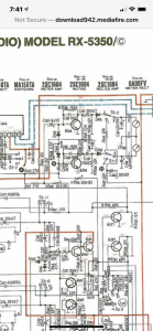
If you look at the B and C junctions of Q204, you'll see R238 and C230 parallel. C230 shouldn't pass DC so if it fails, it will generally either short or OC. If working properly or if failed open, it will have zero affect on your R238 test. If it has failed short, then the V at Q204b should be high but it is NOT so it's safe to presume that an Ω test between B/C Q204 should give the approximate value of R238. If off, lift C leg and retest. If still off, the resistor is bad and you should replace it. To replace, cut one trace leg to R238 or drill out the via that supplies it to take (old) R238 out of circuit. Tack new discrete R238 resistor between B/C of Q204 to complete repair. Make sure in the process you do not inadvertently disconnect R239 from circuit or Q204b will not get bias current and there will be no change. Test R239 in similar manner and adapt this (or other methods detailed in Joes RX5350 thread) to repair if bad. Just remember, even if a resistor is printed, at some point, it will intersect at some standard pad or junction or component. Here's another tip. If you look carefully, you'll see that Q204c, R238, R239 and C231+ shares a common electrical point. Also notice Q204c and C445+. What's in between? Yep, it's R239 right? So even if R239 is printed and maybe even invisible on the board, electrically, you have the schematic so you can figure it out, right? Right.
If you are not understanding the terms or concept of transistor bias, etc, then please google and do some study first, as I'm sure there are tons of information out there and I'm not gonna type all that here. Nowadays, typing for me is very difficult.
Here are some hints and that's all I have to offer, the rest, I leave to you.
If you look at the B and C junctions of Q204, you'll see R238 and C230 parallel. C230 shouldn't pass DC so if it fails, it will generally either short or OC. If working properly or if failed open, it will have zero affect on your R238 test. If it has failed short, then the V at Q204b should be high but it is NOT so it's safe to presume that an Ω test between B/C Q204 should give the approximate value of R238. If off, lift C leg and retest. If still off, the resistor is bad and you should replace it. To replace, cut one trace leg to R238 or drill out the via that supplies it to take (old) R238 out of circuit. Tack new discrete R238 resistor between B/C of Q204 to complete repair. Make sure in the process you do not inadvertently disconnect R239 from circuit or Q204b will not get bias current and there will be no change. Test R239 in similar manner and adapt this (or other methods detailed in Joes RX5350 thread) to repair if bad. Just remember, even if a resistor is printed, at some point, it will intersect at some standard pad or junction or component. Here's another tip. If you look carefully, you'll see that Q204c, R238, R239 and C231+ shares a common electrical point. Also notice Q204c and C445+. What's in between? Yep, it's R239 right? So even if R239 is printed and maybe even invisible on the board, electrically, you have the schematic so you can figure it out, right? Right.
If you are not understanding the terms or concept of transistor bias, etc, then please google and do some study first, as I'm sure there are tons of information out there and I'm not gonna type all that here. Nowadays, typing for me is very difficult.
Generally speaking, metal film resistors are better because they exhibit lower noise characteristics than carbon, but in this case, it makes no practical difference.
Oh, and I forgot to mention... when you test the junctions of Q204, remember that it acts like a diode so depending upon how you have the meter hooked up, you may find one direction with low resistance and a different measurement from the other direction. Ignore the lower measurement and go with the higher measurement. Or ideally, lift one leg of the transistor first. I presumed you already know this, to factor in the transistor in the circuit but if you didn't, then take that into consideration.
Thank you Norm I will be working on it tomorrow since I have off work. I plan on lifting leg for better testingSuperduper said:Oh, and I forgot to mention... when you test the junctions of Q204, remember that it acts like a diode so depending upon how you have the meter hooked up, you may find one direction with low resistance and a different measurement from the other direction. Ignore the lower measurement and go with the higher measurement. Or ideally, lift one leg of the transistor first. I presumed you already know this, to factor in the transistor in the circuit but if you didn't, then take that into consideration.
Norm the resistance was open so I replaced resistor and now I have good resistance but the collector voltage is only about 0.93 v. I know I only scrapped the R238on proper side so R239 should not been affected. I’m looking to see if R239 might be bad to
Just pulled C229 and it checks good.
Collector voltage was fine until adding new R238 resistor. I pulled R238 leg and still get just a 1.33v
Just replaced R239 with no change
I just ordered a transistor because everything seems ok except for the collector voltage
Just pulled C229 and it checks good.
Collector voltage was fine until adding new R238 resistor. I pulled R238 leg and still get just a 1.33v
Just replaced R239 with no change
I just ordered a transistor because everything seems ok except for the collector voltage
Superduper said:"...........To replace, cut one trace leg to R238 or drill out the via that supplies it to take (old) R238 out of circuit. ........... Make sure in the process you do not inadvertently disconnect R239 from circuit or Q204b will not get bias current and there will be no change.....
baddboybill said:Collector voltage was fine until adding new R238 resistor. I pulled R238 leg and still get just a 1.33v
Just replaced R239 with no change
Think about this for a second.... collector voltage was fine (or better) before you worked on it. You said R238 was open so you replaced it and arrived at this point. So you pulled R238 leg (to undo/check making it open again) and it still reads low, which was NOT the case before you worked on it. If transistor was broken before, you would have also had low/no voltage at that time, no? Test ohms between Q204c and C445(+) and see if it reads 2.2k ohms. And how did you replace R239, it's a printed resistor? IF you need to replace it, take R239 out of circuit to prevent parallel resistance and tack new one between Q204c and C445(+).
I actually scraped R239 before replacing and put new R239 between Q204c and C445+... I did this after replacing R238 and testing with and with out R238 leg.
I tested with ohms it went to a number then to 0. When I did same test on Q104c it went to 1.99 and stayed there
Also my Q204c is reading about 1.40v
My Q104c is now reading about 2.35v
I tested with ohms it went to a number then to 0. When I did same test on Q104c it went to 1.99 and stayed there
Also my Q204c is reading about 1.40v
My Q104c is now reading about 2.35v
Wait, you tested R239 in circuit and it went to a number and then 0? And 0 as in zero, or 0 as in infinity? Because these reading discrepencies have nothing to do with Q204. If you don't believe, you can remove Q204 and I believe you will still get the same resistance results. If you have removed R239 (2.2k) and replaced it, but are reading ZERO ohms, you have introduced a short circuit.
What are the voltage measurements from ground (C445-) to the following:
R239 (both sides)
R139 (both sides)
What are running V measurements with Q204c out of circuit?
Same test, but Q204e out of circuit?
Also check C229 with ohmmeter to verify it is not shorted.
What are the voltage measurements from ground (C445-) to the following:
R239 (both sides)
R139 (both sides)
What are running V measurements with Q204c out of circuit?
Same test, but Q204e out of circuit?
Also check C229 with ohmmeter to verify it is not shorted.
I also rechecked The printed R238 and 239 to make sure both are scrapped and open
Ok thank you Norm I accidentally used a 22k instead of 2.2k and meter is now working. I did not see the dot because it was buried so thought it was 22k Thank you again
Ok thank you Norm I accidentally used a 22k instead of 2.2k and meter is now working. I did not see the dot because it was buried so thought it was 22k Thank you again