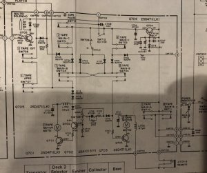
Look, firstly you have the voltages and transistor lead assignments wrong. There's no way I can see that those measurements are correct with regards to Q704. It would only make sense if you have the Collector at 16.22v, Base at 9.94v and Emitter at 9.46v, in which case, everything looks perfect. If I can't trust your measurements or descriptions, or have confidence that you know what you are doing, I won't be able to help you.
Secondly, like I said, both legs of each motor is switched by separate switches. It's easy enough to verify if the first leg (+) is switched properly. Look at SW711. When it is activated, both motors should receive +V at the positive terminal. Put meter probe at that location and operate SW711. This is true if the power switch is OFF. However, when the power switch in ON, both motors will receive +V at the positive terminal regardless of SW711 position. Motor (2) + signal also travels first through the remote jack, which adds another potential source for N/C, but Motor (1) does not so that motors (+) terminal should receive +V if either SW711 or Power Switch is working properly.
Now, moving onto the 2nd leg, which switches the ground through transistor drivers... Motor 2 gets its ground source through Q703. Motor 1 gets it's ground source through Q701 which is triggered by Q702. Again, it's highly unlikely that all of these drivers fail at the same time, so I am doubtful of this scenario. On the other hand, the signal that triggers the drivers involve Switches 701, 702, 703, 704, and possibly 709 all can have some affect on the function. For testing, I recommend that SW709 but set to single (default) position. The switches mentioned here are all low current switches.
So, you have all the information you need here to fix your deck. Can't see how I can be of much more assistance. Perhaps someone else here can chime in.
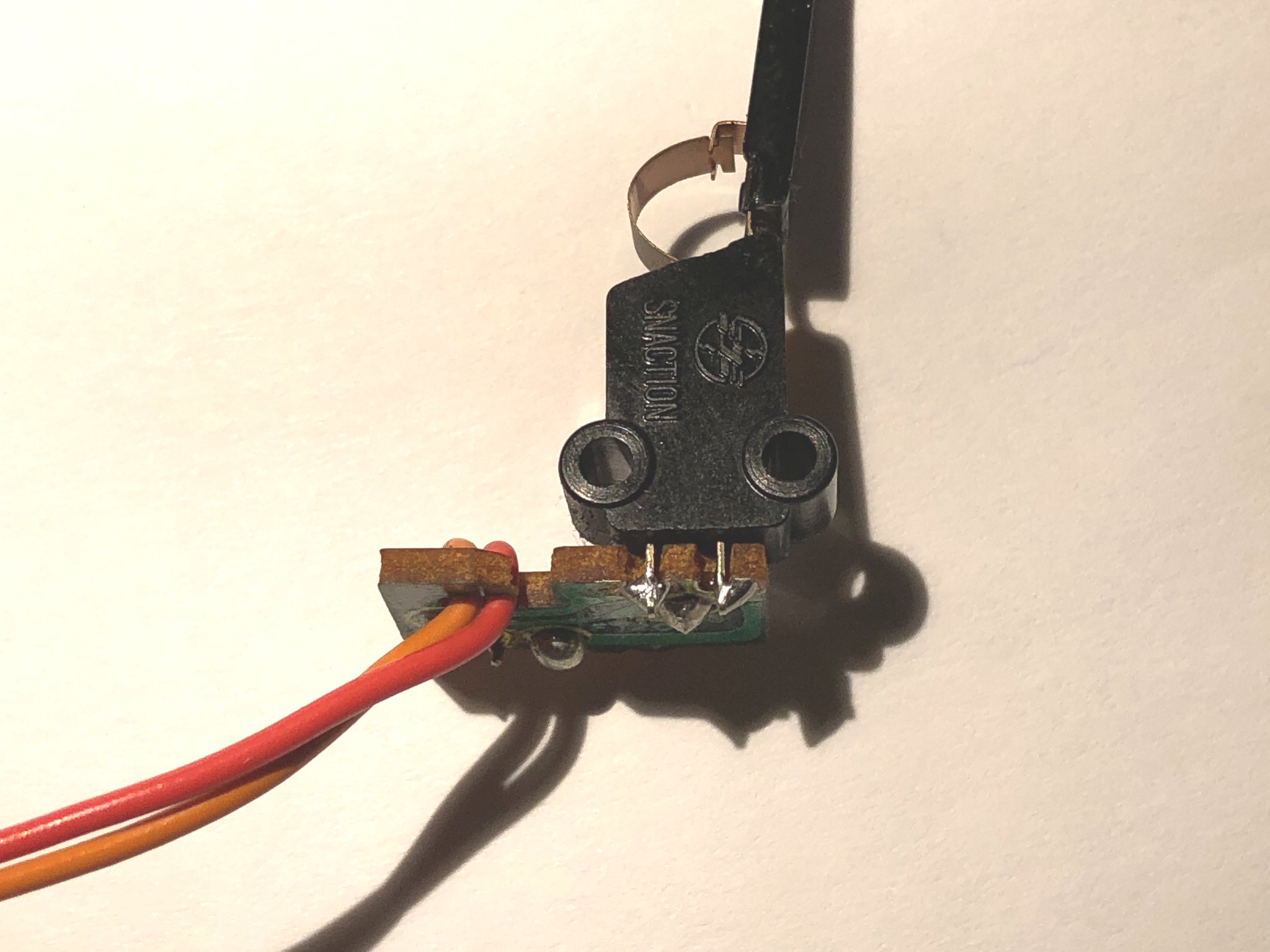
As to your question about buying switches... I personally don't think they are bad or can't be rehabilitated if contacts are merely oxidized. Factory switches are almost surely obsolete now.
So, if you want to do some direct tests on the driver circuits to verify if they are working properly or not, you can do that by injecting a +9v signal to the B of driver Q703 or Q701. But I don't recommend that you do that until you can properly identify the B/C/E of the transistors. Injecting at the wrong lead can cause some damage.
Oh BTW, the driver signals travel through several diodes, and in the case of motor 1, travels through many diodes. If these failed, then operation can be affected and if you like, you can check them with your meter, although I'd suggest that you lift a leg before testing to ensure that some parallel circuit is not giving you false readings.


")