AMP PCB in PQR-9963 aka Silver ST-888

t8ja

New Member
Nov 18, 2018
13
0
1
The
green lines - traces on the other side
red - resistors (and the two yellow ones)
blue - capacitors

red triangles with a red line are transistors "603 21f"
the line denotes BASE with C and E following counterclockwise

The upper red BCE transistor is the one in picture 2, which I can't find in any datasheet repository

The lower BCE is similar to this one https://alltransistors.com/transistor.php?transistor=11812

This is the amp IC https://www.datasheetarchive.com/pdf/download.php?id=0eec90b06c360b470ca33e06bfb139cf4874e0&type=M&term=AN7145


Maybe someone knows the name of this type of circuit ?
It appears to be an expansion of the "basic" one as denoted in the IC datasheet.
 

Attachments

t8ja

New Member
Nov 18, 2018
13
0
1
I'm not sure where the problem is exactly, but the IC is 0K, I checked it by feeding the signal directly at (11 pin strip)
pin 1 and 3 starting from the right, 2 is ground.

The problem appeared while i was switching between modes tape/aux/radio, everything went silent,
actually a slight noise could be heard, but increasing the volume doesn't affect it.
 

caution

Member (SA)
Mar 25, 2014
2,506
341
83
Boomboxery
Hmm. You might want to check that diode, I think it's a zener, which, with the C1368 transistor, forms a regulator. If that blows, nothing else will work.
If it's shorted out, you should check the marking on it to see what voltage zener to replace it with.
 

t8ja

New Member
Nov 18, 2018
13
0
1
You're saying the amplifier would work with the zener being blown ? Because it did work, like I said.. only there was some residual noise after disconnecting the signal, but upon reconnection it sounded fine.
 

Superduper

Member (SA)
The zener diode is part of a voltage regulator circuit that probably powers the preamp or tuner circuits. It almost never has any effect on the output amplifier. So if a zener diode blows, the amplifier, being powered directly via system rail voltage would most likely still work perfectly fine. You should look into maybe cleaning the mode/function switch too. Or the record bar. Hard to imagine that if it was working before, that a zener diode would blow simply by switching modes. You can verify if the zener diode/transistor regulator circuit is working with a voltmeter. Put negative probe on a good ground. Check the end of diode that connects to the base of the transistor. It should read a certain voltage (5, 9, 12, etc). Then put red probe on the collector of that same transistor. It should read similar voltage compared to base (about .6 volts lower). If you get readings like that, the regulator is working fine.
 

t8ja

New Member
Nov 18, 2018
13
0
1
The voltage appears to be the same on both Base and Collector, no drop.
 

Superduper

Member (SA)
Sorry I meant emitter, should be slightly lower than base voltage if regulator is working properly. What was reading? Please report all BCE voltage readings. Same voltage at BC is maybe ok if this was a ripple filter but then it wouldn’t have a zener diode. With the zener diode connected to base, the voltage at that point should probably be whatever the zener voltage is for that diode, which may have failed open circuit. The zener voltage almost never coincides with the supply voltage ( C). You may want to check & confirm it.
 

t8ja

New Member
Nov 18, 2018
13
0
1
Emitter is on ground (through a cap), so how is there to be a drop at all? The traces also go further from the emitter to the 11pin strip (pin 7 and 5), but that was unplugged and I wasn't injecting an audio signal.
 

Superduper

Member (SA)
Ok, first off, the emitter is not on ground. If it was, then because the transistor is an NPN, with voltage at both base and collector, it would be toast. The capacitor in this case acts like a storage or rail stiffener. If you look closely, I think you'll see that it connects to the capacitor (+) pin and not the negative. As this is DC and not AC, the capacitor will block it. Also, it does not matter if the 11 pin strip is connected or not, the regulator will still work regardless. However, I have no idea if this is this is related to, or the source of your problems. I only participated and gave my opinion on the zener diode regulator and how to check it.
 

t8ja

New Member
Nov 18, 2018
13
0
1
looking at the board it certainly is, and it makes sense. It wouldn't be toast, if it's an NPN, bcs the base has to go negative (to ground) for it to conduct from Emitter to Collector (since I like electron current, I see the E as "input" and C as "output", E is always at negative"ground" and C is on positive "Vcc" as you'd call it).

Yes the Emitter is connected to cap(+)pin and that makes perfect sense since ground is on the "other side" of the cap on (-).

The thing is, in this situation the trans isn't conducting because the cap is in the way.
Or should I say, the cap charges up, an then nothing (no current) further happens,
unless it's discharged (which means current).

I've had some time off working on this, but I'm sure of what I've said regarding the general operation of the trans.

I appreciate your input, regardless of how I might "sound", Eng is not my first language.
 

Superduper

Member (SA)
t8ja said:
...........It wouldn't be toast, if it's an NPN, bcs the base has to go negative (to ground) for it to conduct from Emitter to Collector ........... Eng is not my first language.
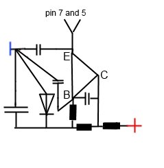
Well, I'll just say this and then I'm out of here. That is a "standard" zener-diode/transistor-driver regulator if I ever saw one and I'm 101% certain you are mistaken about how transistors operate, unless something is lost in translation. In the case of NPN transistors, and the 2SC1368 is in fact an NPN transistor, the base must be more positive with respect to the emitter in order for CE junction to conduct. The way you suggested for base to go neg to ground (in a DC, not dual system) for CE to conduct is how a PNP transistor would work, not NPN; and even in the case of a PNP, the base would needs to be "more" neg with regards to E which if you think about your suggestion, that B and E are both ground, then that scenario would be problematic, would it not? Now when I said the transistor would be toast, read again what I said.... I said "IF" the emitter is connected directly to ground like you suggested, transistor would be toast. That's because with collector and base at + rail, and emitter at ground, with a non-resistive load to restrict current flow, the transistor would conduct and short the +( C) and -(E) (with respect to emitter which again, is at ground per your suggestion).

Going back to post #9, my point was that if C and B are at the same voltage which is what you said you measured, then the zener diode might be blown UNLESS the collector and diode cathode is below zener voltage which is not normal and the resistor that feeds the base and zener cathode might be shorted, and which is why I asked for BCE measurements (you provided none and still haven't). Under normal circumstances, the base should read lower voltage than collector because the base is fed through a resistor, and the zener diode which is also connected to the base should shunt some voltage to ground at the zener voltage of the diode.

Emitter is on ground (through a cap), so how is there to be a drop at all?
Simply by testing the voltage with your DMM will already introduce a load onto the circuit, albeit a small one. Additionally, the transistor itself has internal voltage drop (remember, internally, the transistor behaves like diode, which also has forward voltage drop). Anyway, it doesn't matter. IF your regulator circuit is working properly, collector should be at rail voltage, base should be the zener voltage which is generally lower than rail, and emitter will be approx .5 to .7 volts lower than the base voltage. Just to demonstrate that this isn't BS, I just now quickly rigged up on my portable electronics lab using some generic components, mocked up a zener/transistor regulator with NO LOAD and as expected, the emitter voltage was ~.5v lower than the base. You don't need to think about this unless you have a complete understanding, it simply works.

Anyhow, you've not given the other voltage readings I asked for, in fact, you've given only enough information to not allow us to actually analyze your situation. Clearly have your own ideas about how electronics work, and that's fine but I personally don't have the patience to try to convince you otherwise, so I'll just leave this at that. I do hope you give what I stated some more thought, do some more research about transistors (NPN & PNP) and maybe learned something here.
 

t8ja

New Member
Nov 18, 2018
13
0
1
Turns out that I did get the mechanism wrong, just so it's clear, but the connections are still as I described and as is viewable in the layout. My mixup was in the direction of currents I thought were triggering the transistor, instead of a Electron current running from B to C triggering E to C , it's E to B triggering E to C, which must be obvious to someone dealing with electronics for a long time, but i'm not in that category. Again, Thanks to everybody for responding.

Cheers

and the video that cleared it up for me

https://www.youtube.com/watch?v=rvPV4WZv4ZY

and to do the measuring looking at this the electron way around, + has to be 0 (ground), which I guess shouldn't be much of a mental hurdle. I remember seeing one AvE video where I think he said a forklift he was repairing had the designations aligned to this perspective.