JVC M90 tape deck 12V regulator runs hot

Status
Not open for further replies.

stragulus

Member (SA)
Sep 4, 2014
171
10
18
48
New York
The transistor, Q712, that is part of the 12V regulator on the tape deck PCB, runs quite hot. An infrared thermometer indicates 140+, and it is very hot to the touch. Any idea what I should expect there? Is this clearly way too hot?

To give some context; I've been working on this deck for quite a while (long story for another time). The box it came in had many things wrong with it, and I suspect it may have been overvolted. The tape deck alone had several things wrong it. FR703 was toast, FR704 toasty but still checking OK, Q710 was burnt, Q712 was shorted, the 7V regulator's zener was shorted, etc etc. The capstan motor also ran rough and I've replaced with a temp motor from another boomer. All belts have been replaced with their official sizes. Everything runs fine and stable now. The 12V itself looks nice and flat on a scope. Caps in its path have been replaced. The one thing I'm not sure of is whatever else is powered other than the capstan motor. Looks like in play mode it powers more stuff through S703 (switch in the mechanism).

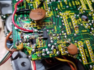
Since someone else has been in here (a pcb's corner was broken for instance, though it didn't interrupt any traces luckily), I wonder if perhaps Q712 had a heatsink of some sorts that is now missing?
 

BoomboxLover48

Member (SA)
Dec 3, 2010
5,756
274
83
Chicago, IL
caution said:
I took a look inside mine, it doesn't have a heatsink.
At 140F(108C) you're probably okay, the datasheet says it's rated for 150C.
Wow! That is pretty hot! :yes:
Never knew a component in boombox can go that high.
EL 84 in tube radios run pretty hot.
I am used to that info...
 

stragulus

Member (SA)
Sep 4, 2014
171
10
18
48
New York
It seems too hot to me, especially since that pcb is tightly packed with components in that corner. Caution, if you still have it open, does yours get as hot? After about a minute in playback mode, mine's just too hot to keep touching which lines up with the temp reading of 140. FR703 that sits right next to it did have a heat shielding 'sock' over it, so maybe they just engineered it like that.. strange, no?
 

Superduper

Member (SA)
That transistor is rated at 1.2a collector current but it probably couldn't do that without some external heat sinking. Perhaps you should verify how much current that circuit is actually drawing. You could perhaps power the motor using an external 12V regulated bench PS in series with the AMP function of your DMM. If the tape transport is not clean and there is excessive drag, it could result in too much current consumption. Also, the fusible resistors should be checked for specs. If the resistance is too high, it could cause the motor to draw too much current. Funny thing about electric motors is that when they are lugged, they draw higher current.

@Eric, the 150c rating is for internal junction temperature, not case temperature.

Because this is a linear type of regulation circuit, the amount of power the transistor will sink depends upon the source voltage. At 15V, the transistor sinks 3V x current draw. If on AC power, this could be almost 20V which means that the transistor will need to sink 8v x current draw... substantially more power and heat. Might be worthwhile to see what the actual source voltage is.

Still, if stragulus feels the temp is concerning, perhaps just clip on a spring clip heat sink and see if this will reduce the transistor case temperature to acceptable levels.
 

stragulus

Member (SA)
Sep 4, 2014
171
10
18
48
New York
Super, thanks for the thorough reply. So initially I put in a 22 ohm for FR703, as the service manual copy that I ordered online was a little blurry there. Those burned up (indeed limiting the current to the motor too much), and I found out it's supposed to be 2.2 ohm. Replaced it with a fusible 1.5 ohm so I think that should be good. Just checked the voltage drop on it, and it's 0.2V, giving a current of about 133mA. DC voltage I measured at 19.7V. Given your 8v * current draw (guess that's source voltage - regulator voltage?), that would make it dissipate about 1W. Seems reasonable, but it seems like the transistor is not up to the task without a heat sink. Running it without one slowly makes the temperature climb all the way up to 160F, after which I stopped. I put on a little aluminum heatsink that I salvaged from a PC power supply, and with that it kept below 140 during a 45 minute play. Guess that will have to do!

You were spot on about the tape transport btw. I think that was the original source of it burning out (although multiple things burned in this box, seemingly related to the DC supply). The capstan motor ran rough. A little sewing machine oil temporarily made it better, but it still didn't run constant so I swapped it out with a temp spare while waiting for an ordered replacement. The flywheel got some new lithium grease where it sits against the plate, and that turns freely without the belt.
 

Superduper

Member (SA)
Yes, the power "sunk" by the transistor is the excessive voltage above regulation. So 20V regulated at 12V results in 8 volts x current sunk in terms of watts dissipated. Or wasted in the form of heat. If the boombox was powered on batteries & source voltage was 15V, there will probably be significantly less heat generated at the regulator.

Virtually all tape transports that are this old have old dried grease. The viscosity usually has become so high that it introduces significant additional drag. Most people just cranks up the tape speed pot to compensate but the motor has to work harder. Unlike you, I suspect that most folks won't bother to feel up the transistors so they likely aren't even aware of the additional stress on the regulators (if one is applicable). Furthermore, if any belt turned to goo, this is like adding glue. After clean up, I usually try to free up all of the moving and sliding parts with a isopropyl needle bottle. By working the moving parts and adding the IPA, (sopping up any dripping fluid of course), most old grease and contamination can be cleaned off. Then new synthetic or lithium grease can be reapplied to the appropriate locations. Sometimes, I see folks just slab new grease over the old. This helps of course but if the old grease is not removed, it's not a good lasting service. I'm glad you are doing it the right way.
 

caution

Member (SA)
Mar 25, 2014
2,508
344
83
Boomboxery
Thanks for clarifying Norm.

I also had a toasty looking FR704, which is the fusible resistor for the solenoid. It would often get too hot to touch within a couple seconds of unit powerup, but every time this happened, I noticed the solenoid was stuck on and the capstan motor was still whirring. The solenoid is only supposed to "kick" on momentarily, perhaps FR704 is meant to fry to avoid over-discharging the batteries, as a safety measure, if it won't disengage?

My best guess is that the solenoid driver, Q711, which is tied to the main control IC, was improperly being told to stay on all the time. It seemed to come down to a bad reflective pattern on the drive gear, which an opto-sensor tied to the control IC relies on. As the drive gear turns, the opto-sensor momentarily receives light from its transmitter LED as it passes over a chunk of reflective material so the control IC knows where in the cycle things are. After I restored the reflective pattern, the solenoid stopped sticking on at powerup, always resetting properly, no more hot FR704.
 

Superduper

Member (SA)
Fusible resistors are installed to protect a circuit when there’s a problem, whether it’s due to shorted motor, excessive current draw from mechanical drag, failed components or in your case, improperly functioning solenoid circuit. That’s why these resistors are always very low values, their primary purpose isn’t intended as current limiting devices but rather for excessive circuit power/time protection. Unlike fuses which blow due to excessive current, these resistors blow due to excessive watts + time. To illustrate, a glass fuse rated at 1-amp is voltage independent. At 1v x 1-amp, there is 1-watt flowing but at 100v x 1-amp, the circuit will flow 100-Watts. Since either are operated within the fuse specs of 1-amp, it does not blow. That would not be the case with fusible resistors. They, are typically rated in watts (i.e., 1/4w, 1/2w, etc) and should remain the same to retain protection. If the proper fusible resistor cannot be found, I would suggest metal film “flameproof” resistors installed by standing off from pcb. This reduces chances of an overheating resistor from catching fire and/or scorching the pcb causing irreparable damage.
 

caution

Member (SA)
Mar 25, 2014
2,508
344
83
Boomboxery
Thanks Norm. I understand how they work and what they do, I just wasn't sure what the risk factor is that warranted one on the solenoid.
 

stragulus

Member (SA)
Sep 4, 2014
171
10
18
48
New York
Superduper said:
Yes, the power "sunk" by the transistor is the excessive voltage above regulation. So 20V regulated at 12V results in 8 volts x current sunk in terms of watts dissipated. Or wasted in the form of heat. If the boombox was powered on batteries & source voltage was 15V, there will probably be significantly less heat generated at the regulator.
I didn't know this, glad to be learning something! On batteries (10xNiMH thus 12V total) it does indeed stay completely cool. Interestingly, one of the last problems I'm solving is that it sometimes turns on in autoplay with the record led on. This does not happen with the batteries as power source. Maybe it doesn't reset properly on AC?

Virtually all tape transports that are this old have old dried grease. The viscosity usually has become so high that it introduces significant additional drag. Most people just cranks up the tape speed pot to compensate but the motor has to work harder. Unlike you, I suspect that most folks won't bother to feel up the transistors so they likely aren't even aware of the additional stress on the regulators (if one is applicable). Furthermore, if any belt turned to goo, this is like adding glue. After clean up, I usually try to free up all of the moving and sliding parts with a isopropyl needle bottle. By working the moving parts and adding the IPA, (sopping up any dripping fluid of course), most old grease and contamination can be cleaned off. Then new synthetic or lithium grease can be reapplied to the appropriate locations. Sometimes, I see folks just slab new grease over the old. This helps of course but if the old grease is not removed, it's not a good lasting service. I'm glad you are doing it the right way.
To be fair, in this case one transistor burned a literal hole through the pcb (Q710, which switches the capstan motor to ground):

20180204_143441.jpg

So I did take more more precautions than usual. Although by then I had already checked the drive's mechanics and cleaned/lubed it. This deck's quite a piece of work if it fails!
 

caution

Member (SA)
Mar 25, 2014
2,508
344
83
Boomboxery
Oh man, it looks like you dodged a bullet with Q710, I had to look at pics of my own board to see if it took out any conductive traces or printed resistors.
 

stragulus

Member (SA)
Sep 4, 2014
171
10
18
48
New York
They all self-destruct like this (presumably when the capstan belt starts giving out)? That's an interesting failure mode.
 

JVC Floyd

Inactive (Delete)
May 6, 2009
7,322
419
83
54
Maryland USA.
It's easy to burn out the fusible resistors in these decks because people turn the power off with the deck still running and it f**** it all up
I know because I did it to mine
.
 

Superduper

Member (SA)
The capstan motor should never draw that much current when in proper operating condition, generally the FR703 should have burned up first. Unless it did and someone replaced it with a non-fusible resistor or even worse, a straight jumper in which case, damage can cascade further down. That the capstan motor was grinding makes me wonder if it wasn't shorting out internally.

In any event, looks like you have it working OK now. However, I see something concerning here which is that you have the new transistor soldered out of place and relying on solder to mechanically secure it. If you notice how scorched the PCB is, a lot of heat was generated in order to burn that hole. You would have a very hard time trying to burn a hole into a PCB with a soldering iron, and we all know what soldering irons are for.... melting solder. So if the transistor ever overheats again, not only will that red wire fall off and potentially short on the board but the transistor itself might fall off. It doesn't take much localized heat to melt solder, far far less than it takes to burn a hole in a pcb. Therefore, when soldering like this, it's far better to solder a mechanically joined connection instead of a connection that relies solely on solder. In other words, use wire wrapped/soldered or mechanical pin terminals whenever possible. It may even be advisible to remotely mount the transistor on a screw standoff and tether it to the board with 3 jumpers using pin-terminals. Also, because the transistor is designed to be in saturation mode, it's really just acting like a switch so substitutes aren't critical. Perhaps a more robust transistor can be used instead which will ensure that toasted/flamed transistor is no longer an issue but does transfer some of the risk to the motor itself. Just food for thought for you to consider.

I've advised readers here time and time again to standoff fusible resistors away from a PCB because of potential scorching or flaming of that component. I'll bet my kitty's litter box that most folks just disregard that bit of advice as highly implausible but your pic demonstrates exactly what I'm referring to.

In the future, perhaps I might consider making a new deck PCB if demand warrants it pre-populated with the common components. The IC's would have to be transferred over of course since those are already NLA new.
 

stragulus

Member (SA)
Sep 4, 2014
171
10
18
48
New York
Thanks for the feedback super! I'll find a nice spot for Q710 to be instead. I had a bigger temp transistor in its place (just any random thing I pilfered from a PSU) which worked fine indeed, I could put that back in its place. I think I still had the original FR703 in place. Whoever worked on it probably gave up after they saw the extensive damage.

I have a few more questions. The old FR703 had a 'sock' on it to shield it from the heat of the nearby transistor (and to prevent it from short-circuiting perhaps). That was charred so I replaced that with a heat shrink tube. Is that safe, or is it flammable / too insulating? if not, what is the old insulation called so I could buy some? Same as for the black tape you often see in these boxes that provide electric isolation. Oh, I also replaced FR703 and FR704 with 1/4W resistors. Worst case they'll burn too soon I figured, would you deem that ok as well?

As to new deck PCB's. Maybe you could consider a halfway solution. Move only the voltage regulators over to a separate board, since they seem to be the biggest culprits. Perhaps it could be done a little smarter as well with a PTC instead of a fusible resistor? I've never designed a circuit like this, but that's what I found as I was investigating. With just the voltage regulators off the deck's pcb it would be easy to modify for most people. You just have to remove some components from the deck's pcb and install a new smaller pcb with a few wires. I guess that still leaves the problem with Q710 though, but I found that one easy to fix, whereas the regulators are really difficult to deal with as they are in cramped areas. A nice in-between solution?
 

Superduper

Member (SA)
I'm guessing that the sock was intended for both insulating it from shorting because it is stood off from the board and not mounted flat on board like most components but also to prevent or reduce risk of flaming up. So it is probably some form of heat resistant fiberglass type of material or similar. I doubt you can find them today in that size. I see some heat shield sleeves but larger size. As for using heat shrink tube, it is fine until it heats up, in which case it will get hard and crusty and possibly can burn up. Burning rubber will not smell good and probably difficult to extinguish too if it catches fire. So if we can't find the proper sock to sleeve it, then we can only improvise since these things are now 40 years old and well past their expected life. Furthermore, technology today has changed and there doesn't seem to be as much need for those socks since circuits today would probably be designed differently. So maybe leave out the heat shrink tubing but then again, if there is no future failure in that circuit it will never become an issue anyhow. The black tape is just electrical tape. Get good ones, not the cheap vinyl ones. as for substituting the FR with standard 1/4 watt resistors.... like I said, you should seriously consider flameproof resistors. You can get them, go to Mouser.com or Digikey and search for flameproof resistors. Getting hot and charring is one thing. Catching fire is something else.

Now, onto the PCB. It's not even worth thinking about unless there is sufficient demand. Just drawing up the circuit itself to be manufactured is quite the chore already but the cost/board simply isn't worthwhile to do unless we buy them in quantity. I'm thinking 50 to 100 boards. As for moving the regulators off the mainboard.... here's the sad truth: NOBODY will buy the board unless their existing board is already damaged, at which time it is probably better to just replace it instead of leaving a damaged board in place and tethering a daughterboard. So getting a boombox collector to part with a few dollars for preemtive preventative and reliability reasons is a high hurdle, but once the deck in their beloved M90 is toast, suddenly, their locks to their wallet becomes a bit looser. This is simply the truth from my experience and observation and not judgmental. As for redesigning using PTC, I don't think that is a good way to go. PTC's regulate by increasing resistance due to excessive current consumption and heat. Increasing resistance to a motor circuit that is struggling to keep up with a load only exacerbates the problem since resistance lowers the torque to the motor which causes it to lug and strain more (an existing excessive load condition is a good possibility that initiated the PTC's to heat up in the first place), and then we have a vicious cycle going and a race to the bottom. Except that the PTC keeps resetting and doesn't fail so performance becomes an issue, motor continues to run and heat up and on and on. It is better therefore, in my opinion, that when a circuit has a problem, that some fuse type device trips or fails and shut things down forcing the owner to investigate the source of the problem and correct it. Toasted resistors are cheap to replace. Perhaps designing the board better and isolating the heat prone resistors so that they can't impart damage when they fail is a better approach. Transistors themselves can be substituted for more robust units that better handle loads without failure.
 

stragulus

Member (SA)
Sep 4, 2014
171
10
18
48
New York
Alright, wrapping up this deck for now. I've relocated Q712 (12V regulator) by flipping it around and mounting it on the solder side, where its heat will not scorch the nearby components. All fusible resistors are actually fusible btw, just 1/4W instead of 1/2, so worst thing they'll go a little earlier. Mostly everything seems to work now including MSS. The only thing left to chase is recording (the left channel records nothing), but that may very well be elsewhere.

I hear you on the PCB issue. No one's going to put in that effort probably, or only a very select set of enthusiasts. Might as well just live with half-charred boards and lots of wiring to work around it, it is what it is.
 
Status
Not open for further replies.