New member with m70

Status
Not open for further replies.

the_hun

New Member
Jan 8, 2018
17
0
1
Hey guys. Nice to be on the forum. I recently acquired a JVC rc-m70 and I would like to restore it as best as possible. However I currently have some issues I need assistance with. First off, the FM stations don't seem to work. The Am stations come in fine. So I'm not sure if the fm switch is malfunctioning or something on the board.
My next problem is that the rewind button on the cassette player does not seem to work. Everything else on the cassette player seems to function fine (I have not tested recording) when I press rewind the cassette turns for like a split second than stops..
I also have the typical slider pot issue as many do. Mine seems to be with the bass slider. I cleaned the contacts inside but actually saw a 3 fingered brass or copper piece loose in there. So I will desolder it and see if I can get in there to rebuild it.
Last but not least what do u guys recommend to use to clean up like pitted and corroded buttons? Mine have some sort of green corrosion on them. Maybe have to end up painting them?

Thanks in advance
 

Superduper

Member (SA)
Sometimes, the green corrosion looks worse than it is. You'll have to decide if the final finish after cleaning-off the corrosion is acceptable or not. I would suggest for cleaning, to first use isopropyl to clean off most of the crusty green oxidation and any accumulated sticky grime. Then final cleaning with some form of polish. Types of polish that might work (each differ in their level of aggressiveness) are:
  • Automotive paint rubbing compound
  • Plastic polish (from tap plastics or equivalent)
  • Brass & Chrome polish (more aggressive)
 

the_hun

New Member
Jan 8, 2018
17
0
1
Yea I'll definitely have to try those things. But I think I'm gonna leave the cosmetic stuff until the end. Once I know if I can get everything in a nice working order
 

Superduper

Member (SA)
@the_hun. I am answering your PM question here on the forum instead.

(1) The X505 regulator has nothing to do with the tuner. Rather the tuner gets it's regulated power through regulator X503. Both AM and FM share the same power rail so that AM is working suggests that the tuner power rail is working fine.
(2) The most likely cause of your condition is degraded contacts within the FM pushbutton switch. The tuning band switches are prone to internal oxidation. It takes very aggressive and persistent cleaning to see results. Sometimes, it may even be necessary to disassemble the switch for effective cleaning but I do not recommend this step as persistent action of the switch while working in deoxidizing contact cleaner is generally effective enough.
(3) This suggestion does not mean that it is for sure the problem as there are probably 101 other possible ways the FM could fail, but this is the most common mode of failure.
 

the_hun

New Member
Jan 8, 2018
17
0
1
Well I took the back cover off and sprayed as much contact electrical cleaner as I could in the switch an worked it for quite a while. Still nothing. I'm in Canada and never seen this deoxit product but I figure the contact cleaner should have got me somewhere. I guess the search continues lol
 

the_hun

New Member
Jan 8, 2018
17
0
1
Ok so far I have fixed the rewind problem.. There are 2 rubber band type things that surround the plastic wheels which the cassette turns on. 1 of them snapped and separated and every time the wheel turned it would jam on that friction center wheel. A temporary fix of crazy glue holding the band together seems to have the problem solved as it rewind without issues now. So cassette deck is fully functional! Anyone know where to find d those little rubber wheel surrounds?
Now to find the fm tuner problem..
 

Superduper

Member (SA)
Idler pulley rubber can sometimes be replaced if an appropriately sized "O" ring can be located. Although they don't have flat surfaces once installed, nevertheless, they do seem to work.

As for the tuner, oxidized band selector switch is by far the most common mode of failure. If you are certain that the problem is not with that switch, then the process to discover the failure is far more complicated and probably requires equipment that most folks don't have. As a start, you can acquire the service manual and then do voltage checks at test point locations to see if they are within specs. Voltage checks are employed as a diagnostic technique since failed components usually skews the voltage from spec at the prescribed locations. That doesn't necessarily mean that a component with improper voltages readings are themselves bad. But through studying of the circuit diagram, it does allow one to interpret the readings and better narrow down potential culprits. For DIYers that have no diagnostic ability, then swap and replace is an option. You won't be able to determine the exact failed component without diagnostic skills but I can tell you the following:

Active components in the FM path:
IC2
IC1 (shared with AM)
X1
X2
X3

Passive components are far more numerous and I won't bother to enumerate them here. They can be viewed on the circuit diagram.

You can shotgun them if you wish but be forewarned... original semiconductors are mostly all no-longer-available and if they can be found, and located on eBay, there is a very good chance that they are china counterfeit or clones. Many will not work properly in the highly fussy circuitry of tuner applications. For this reason, if you shotgun all the active components, and one or more don't spec correct (or even possibly don't work at all), then not only will there be no improvement but you could potentially have complicated matters further because you removed all the good working ones with suspicious ones. This could create a future diagnostic nightmare. Why? For example, transistors in tuners are often rated in terms of bandwidth and spec'd for VHF or UHF operation. But those aren't characteristics that are generally tested for, or even easily checked. So in an inoperative circuit, one might remove a transistor for testing and find that they test good, but as installed, doesn't work. Simply testing for proper operation and HFe (beta) might suggest that the transistor is OK and it might indeed work fine as a switch or as an audio amplifier but may not be able to deal with RF.

Bottom line. Unless you are well versed in troubleshooting circuitry, and if you've concluded that the band switch is OK, you may be better off farming a tuner repair to a professional. If you really want to give it a try, then try replacing IC2 first.
 

the_hun

New Member
Jan 8, 2018
17
0
1
Thanks Norm. I would like to do a continuity test first on the switch but the only 2 soldered joints on the back side don't seem to be of much help unless I might be checking the wrong spot somehow.. Lol. Ironically before I picked up this stereo I sold my dad's oscilloscope that I had under my bench.. Thinking when in the world would I need or use this. Haha. My dad was in the tv/radio and electronics repair business for over 30 years. He owned his own shop. If I can't find the solution with ur guidance I might have to turn to him to take a look as he definitely has the experience. However he gets back from his snowbird vacation at the end of the month. I'll report back to you soon
 

the_hun

New Member
Jan 8, 2018
17
0
1
Ok so my An7410 fm chip was bad. Ordered a new one and it's on its way.
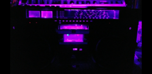
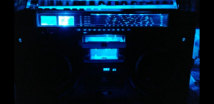
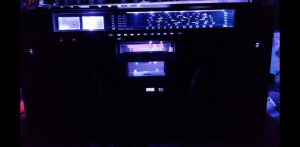
Now for my next question. Where can I tap into a good 12v source on this box? I have an led light kit setup which looks amazing. But during radio playing I get interference from the transformer that came with the led kit.
 

Attachments

Status
Not open for further replies.