I picked this Sanyo up a while back and it’s been sitting in the pile of boxes for repair. I was put off to a degree by its reputation of being a complete bitch to rebelt. Well I’ve got a bit of time off around Christmas and I thought I’d give it a go. I read a few tips on here and dived in.
It’s in reasonable nick and looked complete.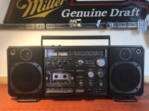
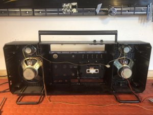
Within half an hour the chassis was out")
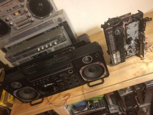
Got to the deck and found the main flat belt was really loose so replaced that. Bit fiddly getting the belts (there are three) back on in limited space but this was the hardest bit.
Got a broken stop/eject key so waiting for the glue to set before reassembly and testing but it wasn’t half as hard as I’d thought...so if you have one and have put off rebelting it then don’t! Dive in and get it done
And if you want to know how to do it just follow the wise words of BoomboxLover48 that I’ve copied below and is all you need
................................................
Disconnect power cord. Remove all the knobs from the front. Open the cassette door, leave it open.
Remove all the back cover screws. Two are hidden in the cassette compartment.
Gently pull out the rear cover because there are several connectors and wire pins to remove.
Looking from the top take pictures of these connectors and mark them.
Antenna connectors and two yellow wire connectors can be easily pulled out holding on the PC board.
On the top right corner you can see the speaker wire 4 pin connector, unplug it.
Once all the connectors from the rear cover top area is removed , lay the rear cover on it's back.
The power lead 4 pin connector goes to the right bottom corner, unplug it.
Now the rear cover can be separated from the front.
Now we are ready for the chassis removal.
On the right side under the speaker a small PC board needs to be removed before taking the chassis out.
Lift the top push buttons and rotate one clockwise and the other anti clockwise, they will stay up locked in a slot. This step is very important or else will break the switches.
Chassis mounting screws can be seen along the rim of the chassis. Once they are all removed chassis will come out easily. Take care not to hold any area of it where the tuning cord is running, also on the tuning wheel gang assembly.
By moving wires around it it can be positioned on a micro fiber cloth buttons and dial plate facing down.
Now start working on partially moving/separating the main board up to get access for belt replacement.
The PC board with cassette controls next to the motor is mounted on a steel plate. This plate is mounted on the metal frame with two small screws. It is a bit of struggle to find the right Philips screw driver tip to unscrew them.
There are white plastic pin tips on the head of the cassette function switches. These plastic tips will fall backwards. There tips need to be re positioned before putting it back.
Before one removes the mounting screws of the mail amp board this cassette control board has to be removed from the metal chassis.
There are several plastic ties securing wire bundles on the side of the main amp board. Untie them before lifting the board slightly up. Lift the main PC board gently and separate like 3 inches.
Use a foam wedge to keep it separated to gain access to the cassette flywheel cover area.
The lower sections of the deck are is now clearly visible.
Two screws hold the flywheel cover. The flywheel cover can be easily removed, but watch the belt guide on it. The new belt has to channel through that cut section on the side of the flywheel cover.
There are altogether 3 belts there to replace. The smallest square belt goes from the small axis pulley of the flywheel to a small plastic pulley. The main flat belt goes from the motor pulley to the flywheel. The other belt connects the middle part of the flywheel to another almost same size plastic pulley.
It is a little tricky to get these belts in position starting with the main flat belt. I used plastic tools to put those belts in place.
It’s in reasonable nick and looked complete.
Within half an hour the chassis was out
Got to the deck and found the main flat belt was really loose so replaced that. Bit fiddly getting the belts (there are three) back on in limited space but this was the hardest bit.
Got a broken stop/eject key so waiting for the glue to set before reassembly and testing but it wasn’t half as hard as I’d thought...so if you have one and have put off rebelting it then don’t! Dive in and get it done
And if you want to know how to do it just follow the wise words of BoomboxLover48 that I’ve copied below and is all you need
................................................
Disconnect power cord. Remove all the knobs from the front. Open the cassette door, leave it open.
Remove all the back cover screws. Two are hidden in the cassette compartment.
Gently pull out the rear cover because there are several connectors and wire pins to remove.
Looking from the top take pictures of these connectors and mark them.
Antenna connectors and two yellow wire connectors can be easily pulled out holding on the PC board.
On the top right corner you can see the speaker wire 4 pin connector, unplug it.
Once all the connectors from the rear cover top area is removed , lay the rear cover on it's back.
The power lead 4 pin connector goes to the right bottom corner, unplug it.
Now the rear cover can be separated from the front.
Now we are ready for the chassis removal.
On the right side under the speaker a small PC board needs to be removed before taking the chassis out.
Lift the top push buttons and rotate one clockwise and the other anti clockwise, they will stay up locked in a slot. This step is very important or else will break the switches.
Chassis mounting screws can be seen along the rim of the chassis. Once they are all removed chassis will come out easily. Take care not to hold any area of it where the tuning cord is running, also on the tuning wheel gang assembly.
By moving wires around it it can be positioned on a micro fiber cloth buttons and dial plate facing down.
Now start working on partially moving/separating the main board up to get access for belt replacement.
The PC board with cassette controls next to the motor is mounted on a steel plate. This plate is mounted on the metal frame with two small screws. It is a bit of struggle to find the right Philips screw driver tip to unscrew them.
There are white plastic pin tips on the head of the cassette function switches. These plastic tips will fall backwards. There tips need to be re positioned before putting it back.
Before one removes the mounting screws of the mail amp board this cassette control board has to be removed from the metal chassis.
There are several plastic ties securing wire bundles on the side of the main amp board. Untie them before lifting the board slightly up. Lift the main PC board gently and separate like 3 inches.
Use a foam wedge to keep it separated to gain access to the cassette flywheel cover area.
The lower sections of the deck are is now clearly visible.
Two screws hold the flywheel cover. The flywheel cover can be easily removed, but watch the belt guide on it. The new belt has to channel through that cut section on the side of the flywheel cover.
There are altogether 3 belts there to replace. The smallest square belt goes from the small axis pulley of the flywheel to a small plastic pulley. The main flat belt goes from the motor pulley to the flywheel. The other belt connects the middle part of the flywheel to another almost same size plastic pulley.
It is a little tricky to get these belts in position starting with the main flat belt. I used plastic tools to put those belts in place.


 ~ Royce