Sanyo M-X650 with broken power board

Status
Not open for further replies.

BoomboxLover48

Member (SA)
Dec 3, 2010
5,752
271
83
Chicago, IL
Another bad luck with a nice Sanyo! :sad: :sad: :sad:

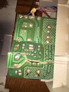
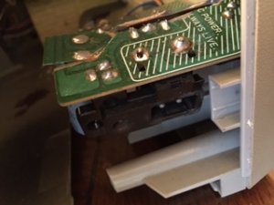
My poor Sanyo M-X650 arrived with a broken power PC board. Seller packed it with the AC cord plugged in the socket. During shipment that side with the plugged AC cord hit on one side, and pushed the cord to completely inward and broke board at 5 pieces. :bang:
I tried to connect with jumper wires and it had 14.5V. Later when I put the board with transformer into the unit it had issues.
I again went through the jumper connections to check for any breakage and found none. Now I get a DC output of 0.932 V.
The secondary of the transformer shows 13.48V AC. There is a break in the rectifier circuit somewhere.
The power supply of this Sanyo is not complicated like other boxes. It is a very simple circuit, but I find it hard to find the problem.

I don't have a manual for Sanyo M-X650.
 

Attachments

Fatdog

Well-Known Member
Staff member
May 3, 2009
10,900
129
63
Oh, man, that sucks! I remember when I got my M-X720 in the mail, the power board was broken, but nothing like yours. I think I only had one trace to solder.

Good luck with the fix, Royce. :yes:
 

JVC Floyd

Inactive (Delete)
May 6, 2009
7,322
419
83
54
Maryland USA.
I repaired power boards broken much worse than that I would double and triple check all your repairs and look for anything you might have missed.
 

BoomboxLover48

Member (SA)
Dec 3, 2010
5,752
271
83
Chicago, IL
Fatdog said:
Oh, man, that sucks! I remember when I got my M-X720 in the mail, the power board was broken, but nothing like yours. I think I only had one trace to solder.

Good luck with the fix, Royce. :yes:
Thanks Bobby!

I've repaired boards those were much worse than this. This was working after my fix and then something happened. I need to check it out.

JVC Floyd said:
I repaired power boards broken much worse than that I would double and triple check all your repairs and look for anything you might have missed.
Thanks Floyd! It was working after I did the jump wires and later something happened. Ouch!
 

BoomboxLover48

Member (SA)
Dec 3, 2010
5,752
271
83
Chicago, IL
I am getting 16.28V DC. :-D :clap:

Finally I am getting 16.28 V, DC from the plug in AC line. It is 13.5 V with batteries.

Is this the input voltage for the main board? Please advice

Per Floyd's suggestion I was looking for every single connection and found a line that no one would think it is broken.
 

Fatdog

Well-Known Member
Staff member
May 3, 2009
10,900
129
63
I would think you would be okay with 16.28V if the box itself is rated as 15V. However, I'm sure someone such as Norm would know better than I would.

Congratulations on getting it fixed! :thumbsup:
 

BoomboxLover48

Member (SA)
Dec 3, 2010
5,752
271
83
Chicago, IL
Checked my line voltage and it is 124 V. It is on the 120 V tap reading 16.28 V DC.

Used a step down AC transformer and tested it.

All working now. Tape had no sound but a good cleaning on the record switch made it sound like new.


Now I have a very good looking Sanyo M-X650.

This thing rocks! Can't go over 1/3 of the volume....so loud! :thumbsup:

Fatdog said:
I would think you would be okay with 16.28V if the box itself is rated as 15V. However, I'm sure someone such as Norm would know better than I would.

Congratulations on getting it fixed! :thumbsup:
Thanks Bobby!
Thanks Floyd!
:bow:

I was so hopeless at one stage and got determined to check every line one more time per Floyd's advice. It worked!

Will post pictures soon!
 

T-STER

Member (SA)
Jul 14, 2014
2,246
73
48
UK
That board looked well farked, good job in getting it up and running again bro :clap:
 

BoomboxLover48

Member (SA)
Dec 3, 2010
5,752
271
83
Chicago, IL
Thanks bro! Never gave up. Used epoxy glue at the cracks and it all looks nice now except for too many wires flying around. This is one of the best sounding boxes made by Sanyo! It is so loud at 1/3 volume. Don't know the power in watts per channel for this one.
 

JVC Floyd

Inactive (Delete)
May 6, 2009
7,322
419
83
54
Maryland USA.
I had one of those before was a very nice radio , one thing you do can do to stabilize that power board is coat one side of the power board with J-B Weld and it locks everything into place once its dry it works like a charm. Glad you got it up and running I don't like messing around with electricity so I always double and triple check everything.
 

JVC Floyd

Inactive (Delete)
May 6, 2009
7,322
419
83
54
Maryland USA.
BoomboxLover48 said:
I am getting 16.28V DC. :-D :clap:

Finally I am getting 16.28 V, DC from the plug in AC line. It is 13.5 V with batteries.

Is this the input voltage for the main board? Please advice

Per Floyd's suggestion I was looking for every single connection and found a line that no one would think it is broken.
Usually it's one of the legs of the Transformer I had this happened so many times I always have to look around the bottom of the transformer over to make sure nothing's broken.
 

BoomboxLover48

Member (SA)
Dec 3, 2010
5,752
271
83
Chicago, IL
JVC Floyd said:
I had one of those before was a very nice radio , one thing you do can do to stabilize that power board is coat one side of the power board with J-B Weld and it locks everything into place once its dry it works like a charm. Glad you got it up and running I don't like messing around with electricity so I always double and triple check everything.
Very good advice Floyd! Attention to detail is the key!
 

Superduper

Member (SA)
Fatdog said:
I would think you would be okay with 16.28V if the box itself is rated as 15V. However, I'm sure someone such as Norm would know better than I would.
Bobby, power supply design like this for a 12v boombox would usually be around that 17v. Being that this is a 13.5v boombox, I would have expected to see 17v or more, but I am guessing that this particular power supply is based around a 12v power transfomer. With a full-wave bridge rectifier and a smoothing capacitor, the usual output for such circuit would be 16.92v which is close to what Royce is getting so I am presuming that's what was used here. For the curious, the reason why the DC voltage is showing that amount is because this is a peak voltage due to the filter capacitor charging up but the average will only be 90% of the AC secondary voltage. This power supply setup is probably the same as that found on the M9994 (12v boombox) as that one also outputs ~17vdc.

Royce, if that was my power supply, I would probably just make a new PCB. Now would be a good time to learn to make a new PCB using either of several simple methods, the simplest of which is to literally just draw the layout you want using a special masking sharpie, and then soaking the blank PCB in an etching solution. If kept warm, in a short period of time, the unmasked areas are etched away and you will be left with the masked portions which can be cleaned off with isopropyl. Drill the holes and you are ready to re-populate the board. Making a more complicated circuit with fine traces is difficult but a power supply with big heavy traces and very few components is about as easy as you can get.
 

BoomboxLover48

Member (SA)
Dec 3, 2010
5,752
271
83
Chicago, IL
Superduper said:
I would think you would be okay with 16.28V if the box itself is rated as 15V. However, I'm sure someone such as Norm would know better than I would.
Bobby, power supply design like this for a 12v boombox would usually be around that 17v. Being that this is a 13.5v boombox, I would have expected to see 17v or more, but I am guessing that this particular power supply is based around a 12v power transfomer. With a full-wave bridge rectifier and a smoothing capacitor, the usual output for such circuit would be 16.92v which is close to what Royce is getting so I am presuming that's what was used here. For the curious, the reason why the DC voltage is showing that amount is because this is a peak voltage due to the filter capacitor charging up but the average will only be 90% of the AC secondary voltage. This power supply setup is probably the same as that found on the M9994 (12v boombox) as that one also outputs ~17vdc.

Royce, if that was my power supply, I would probably just make a new PCB. Now would be a good time to learn to make a new PCB using either of several simple methods, the simplest of which is to literally just draw the layout you want using a special masking sharpie, and then soaking the blank PCB in an etching solution. If kept warm, in a short period of time, the unmasked areas are etched away and you will be left with the masked portions which can be cleaned off with isopropyl. Drill the holes and you are ready to re-populate the board. Making a more complicated circuit with fine traces is difficult but a power supply with big heavy traces and very few components is about as easy as you can get.
Great advice dear Norm!

Sanyo made the simplest power board of all. It didn't take much time for me to figure out the rectifier stage. I was so frustrated at one time when it all worked, and then didn't. That was the time I was about to check components one by one, but made one more (4 times or more) check per Floyd's advice.

Anyway, now the DC voltage from our Chicago 125 V AC line ( 120 V tap) what I get is 15.95 V from the power supply.

I am so tired.....I spend hours fixing it all....even the tape deck! Deck had no sound...a good cleaning on the record bar made it work like new. ~Royce
 
Status
Not open for further replies.