Need Help Reversing Some Nasty Hacks

Status
Not open for further replies.

superlew

Member (SA)
Apr 22, 2012
1,087
3
0
44
Woburn, MA
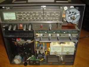
I think I need some help...
I popped open the 'Funken 1M this weekend and was surprised at what I found.

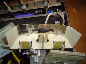
1st off, the VU's were just resting against the face to keep them in. After a long search (I'm not a S2G member) I found a S2G post with a couple of pictures of the main unit with the face removed. I saw that there is supposed to be a plastic piece that acts as both a reflector for the light and holds the VU's in place. I'd love some detailed pics of the piece, if anyone has some ("guts" pics seem to be pretty rare for the HIFI Studio units). I'm thinking of making a mount/reflector myself from aluminum - just thinking about it.
I also noticed that all the lights, other than the ones for the tuner dial, have all been carelessly ripped out. Not a problem, since I'll be doing an LED conversion

Here are the VU's in their current state while I have this thing open:
20161205_154118.jpg

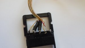
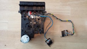
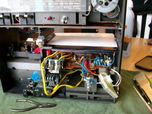
Next, I'd like to know where this loose spade connector goes to:
20161205_154009.jpg

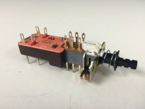
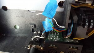
Finally, my biggest issue are these loose wires near the power switch and front jacks - pretty sure they're related to battery charging:
20161205_154058.jpg

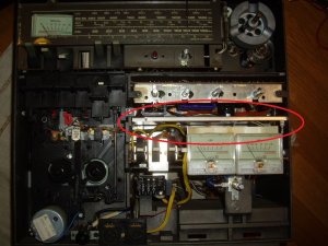
I traced the blue wire (pay no attention to little flag labels I made) back to the 12V power input.
The white wire goes to the (-) battery terminal.
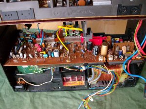
The red and green wires go back to the board for the deck, but I can't really chase the exact position on the board without removing it, which I'd like to avoid.

I found a picture of the top of the power switch on some Russian site, but the resolution was really bad - Like some of my pictures!

I have the service manual (freebie), but it's either poorly written or it's missing content. It's just so difficult to trace a circuit when the diagrams and scheme's are spread out over multiple pages in PDF.

Any photos and/or advice would be greatly appreciated. I rarely reach out here, but I think I'm getting lazy as I get older.
I can't believe I was silly enough to run this thing with all the loose wires inside - I know better than that. :nonono: :dunce:

Other than all the BS noted above, it works and sounds great.
 

baddboybill

Member (SA)
Jul 14, 2009
11,091
84
48
55
Hudson Florida
Very cool as the Telefunken is the baddest 3pc I've ever owned. Wish I took pics of mine when I took it apart to help you out but of course I didn't hopefully somebody else chimes in sorry !!!

Looks someone cut the wires!!!
 

superlew

Member (SA)
Apr 22, 2012
1,087
3
0
44
Woburn, MA
baddboybill said:
Very cool as the Telefunken is the baddest 3pc I've ever owned. Wish I took pics of mine when I took it apart to help you out but of course I didn't hopefully somebody else chimes in sorry !!!

Looks someone cut the wires!!!
You ain't kiddin', Bill...
I think they were using tin snips and a rusty screwdriver, fueled by one or two stiff drinks.
 

superlew

Member (SA)
Apr 22, 2012
1,087
3
0
44
Woburn, MA
Well, after another Google Image search, I was able to find some fairly *acceptable photos of the inside of the HiFi Studio.
They're not great, but they certainly gave me a decent point of reference,
The dangling grounding wire with the spade connector is actually supposed to be connected to a shield that is missing in my HiFi Studio.

Here's one of several pics I found (not mine):

IMGP13402.jpg

So it looks like I'll be doing some minor sheet metal fab, which is right up my alley - just too damn cold out to be bending metal on the brake today. Maybe I'll start keeping it in the kitchen, since this thing is missing a few other parts that I'm perfectly capable of manufacturing.

I'll keep posting my progress, although it's going pretty slowly with the upcoming holidays.

Again, if anyone has a good pic of the power switch installed and intact it would be greatly appreciated.
 

baddboybill

Member (SA)
Jul 14, 2009
11,091
84
48
55
Hudson Florida
superlew said:
Well, after another Google Image search, I was able to find some fairly *acceptable photos of the inside of the HiFi Studio.
They're not great, but they certainly gave me a decent point of reference,
The dangling grounding wire with the spade connector is actually supposed to be connected to a shield that is missing in my HiFi Studio.

Here's one of several pics I found (not mine):

IMGP13402.jpg

So it looks like I'll be doing some minor sheet metal fab, which is right up my alley - just too damn cold out to be bending metal on the brake today. Maybe I'll start keeping it in the kitchen, since this thing is missing a few other parts that I'm perfectly capable of manufacturing.

I'll keep posting my progress, although it's going pretty slowly with the upcoming holidays.

Again, if anyone has a good pic of the power switch installed and intact it would be greatly appreciated.
Someone was definitely in this unit and most likely rigged things!!!
 

superlew

Member (SA)
Apr 22, 2012
1,087
3
0
44
Woburn, MA
I finally got back to the 1M, since I'm stuck inside with a snow storm (I know, Bill - It's not snowing in FL :lol:
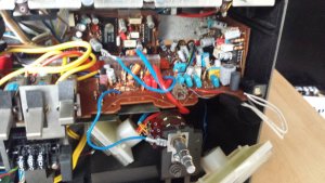
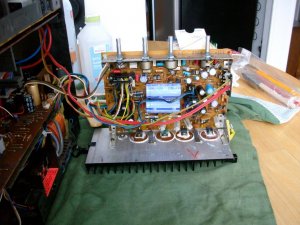
). I'm finding that the tear-down is not nearly as bad as I though it would be. The terrible prior work threw me off a bit, thanks to all the random wires to pin connectors running every which way through the unit. Once I removed each section (boards, etc.), the wire routing became very clear.
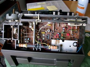
I'm making progress.

I did fashion up a new aluminum version of the missing grounded shielding plate that was missing from some scrap from work- nothing fancy - just functional. I also made a prototype reflector for the VU's, but I'll show that and the final product when I get around to posting a resto thread.

Here are some decent pics of the "guts", since hi-res "guts" pics are pretty hard to come by.:

A good look at the top of the tuner board after a cleaning.:
SANY1112.JPG

Amp removed from chassis.:
SANY1113.JPG

A good look at the deck board after removing the amp and Hi-Com boards (They just plug directly into pin connectors on the board shown).:
SANY1114.JPG

Finally, here's the very simple shield, temporarily installed, that I whipped up at the kitchen table.:
SANY1115.JPG


I'm trying to keep this thread as "techy" as possible without it turning into a resto thread. I thought it might be helpful to other members or future members to see some high-quality "guts" pics. I'll be sure to update the thread when I get around to the power switch, but right now I have a glass of wine with my name on it that's not going to drink itself.
:-D
 

superlew

Member (SA)
Apr 22, 2012
1,087
3
0
44
Woburn, MA
baddboybill said:
Looks good so far. Hopefully you get this badboy back and working fully. :-)
Thanks Bill. As busy as I've been for the last several months, I was a little nervous to dip in, thanks to what I found from the initial opening. I'm finding the 1M to be a lot more service-friendly than I had initially thought. In good time I'll have it 100%. I've already heard the sound that comes out of it, so I'm a little anxious to get it done, but I only live in a 24-hour-a-day world and I'm pushing 30 hour days lately.

BoomboxLover48 said:
Arom, Here is a pic I just found from a search.
Thanks Royce. I actually have a copy of that pic. According to the pic, it looks like all the leads end at the same point, but I'd like 1 or 2 other decent pics (preferably hi-res close-ups) to confirm. The wires were all twisted together and taped when I opened it up and they looked like they were poorly soldered together, so I'm starting to think that's the case. The switch has obviously been heavily tampered with.

This snow storm is turning me into a serial poster! :w00t:
 

superlew

Member (SA)
Apr 22, 2012
1,087
3
0
44
Woburn, MA
Thanks to member stevenrob a couple of weeks ago, I was able to confirm that the correct power switch would be the SDU3P TV-3 package.
I was unable to find a part number in the service manual, so stevenrob's photo was invaluable. When I compared the 1M schematic to the function of the SDU3P package, I knew I had my part. They're no longer in production, but I found a seller on eBay that has a few NOS. I found that it's a very common switch in many hifi receivers.
The switch I removed was a simple push-button toggle that was broken and a little dangerous to be switching 120V, in my opinion. It went out with the trash yesterday morning.

SDU3P TV-3 Switch (eBay pic):
sdu3p.JPG
 

superlew

Member (SA)
Apr 22, 2012
1,087
3
0
44
Woburn, MA
Below is a picture of the of the playback/record head wires (sort of) attached to their respective pin connector points. When I started unplugging the connectors to remove the large deck board, the head wires just pretty much started falling off of the connector. I decided to try and remove them, strip them back, and re-solder them. But I found the wires just kept pulling out of the insulation. There seemed to be some sort of corrosion issue, where the copper was incrementally corroded and weak. If you look carefully, you can even see the corrosion on the ground wire through the insulation. No idea how this could occur, since there is no evidence of water or moisture damage to the unit.
Anyway, I just so happened to have a full head assembly from a Sharp component deck that I cannibalized for parts. I've since replaced the original wires with the "new" wires from the Sharp deck and they went on without a problem.
Anyone seen this type of failure before? Just curious. I'll post pics of the completed wire swap when I get home tonight or tomorrow. Nothing compelling - Just different colored wires.

20170309_160532.jpg
 
  • Like
Reactions: dubout

baddboybill

Member (SA)
Jul 14, 2009
11,091
84
48
55
Hudson Florida
superlew said:
Below is a picture of the of the playback/record head wires (sort of) attached to their respective pin connector points. When I started unplugging the connectors to remove the large deck board, the head wires just pretty much started falling off of the connector. I decided to try and remove them, strip them back, and re-solder them. But I found the wires just kept pulling out of the insulation. There seemed to be some sort of corrosion issue, where the copper was incrementally corroded and weak. If you look carefully, you can even see the corrosion on the ground wire through the insulation. No idea how this could occur, since there is no evidence of water or moisture damage to the unit.
Anyway, I just so happened to have a full head assembly from a Sharp component deck that I cannibalized for parts. I've since replaced the original wires with the "new" wires from the Sharp deck and they went on without a problem.
Anyone seen this type of failure before? Just curious. I'll post pics of the completed wire swap when I get home tonight or tomorrow. Nothing compelling - Just different colored wires.

20170309_160532.jpg
Very cool you found replacement wires.
 

superlew

Member (SA)
Apr 22, 2012
1,087
3
0
44
Woburn, MA
Here's the head re-installed with the "new" wires from an old Sharp deck.

20170310_155018.jpg

Of course, one of the brass tabs that hold the wires in place broke from prior fatigue. I was able to salvage what remained and was able to use it to solder the ground wire. I also found that the (+) lead to the erase head was nearly flapping in the breeze. Looks like someone broke it and tried to twist the wire around the lead. Yeah, I fixed that, too.
I'll tell ya, fixing these hacks is getting really old. :annoyed: I mean, peeling back the years and replacing out-of-spec aging components is one thing, and a part of the restoration process I find enjoyable. Repairing shoddy work is a whole different level of frustration that I hope not to deal with again any time soon.
 

stevenrob

Member (SA)
Sep 6, 2016
282
2
18
France, North
OK ! If you need photos, ask me. My telefunken is now disassembled because the sound is bad with high com position and I'm changing all the capacitors of the 2 high com boards. I have also changed the capacitors of the speakers.
 

superlew

Member (SA)
Apr 22, 2012
1,087
3
0
44
Woburn, MA
stevenrob said:
OK ! If you need photos, ask me. My telefunken is now disassembled because the sound is bad with high com position and I'm changing all the capacitors of the 2 high com boards. I have also changed the capacitors of the speakers.
Thanks, stevenrob. I'll let you know if I need any.
I was hoping to replace all the gray (Eccom) caps in mine yesterday, but my order never arrived due to a snow storm. They should be here today, so I should feel like I'm making progress again by this evening.
 
Status
Not open for further replies.