Hitachi 3d7 MKII noise

IVH

Member (SA)
Jul 4, 2016
58
0
0
Hello,
I recently bought a hitachi 3d7 MKII from ebay, it is in great state: everything works and it looks amazing, scratches are hard to be found. I'm going to install a bluetooth module and a lipo battery (while keeping it original, of course).
When I received it, I noticed all sliders were stuck, a little cleaning and contact grease/cleaner fixed that. But the buzz/noise was still there...

I did some research here on Boomboxery and found what has to be known to isolate the problem:

-it happens on the left and right channel + with headphones
-noticeable when on batteries
-the noise gets louder when turning the volume up
-it can be filtered out using the equalisers
-it is even noticable when nothing is connected (tape deck disconnected from main board, no line-in connected)
-clearly hearable when playing music through the cassette deck or line in.
-the resistance between the ground of the power supply is 0 Ohm to all 'grounds' I measured on the board
-If I touch the ground when it is powered on, there is much more noise (this might be normal?)

Please tell me if I'm wrong:
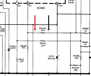
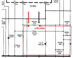
The issue lays after the power supply and before the equalisers. And maybe even before the 3 different amplifiers (?).
Unfortunately I can't find a service manual to download, does anyone know where to find one ?
Where do you think the problem is most likely to lay ?

Thanks in advance,
ivh
 

Fatdog

Well-Known Member
Staff member
May 3, 2009
10,898
112
63
Welcome aboard, IVH! Before any technical advice from other members, I would suggest sending a PM to member isolator42. He is pretty much the goto guy with all things Hitachi 3D.
 

isolator42

Member (SA)
May 6, 2009
239
0
16
55
Surrey, UK
Hi there,
I might be a big fan of the 3Ds, but I'm no electronics expert, unfortunately. It sounds like you already know more than me - from what you say it sounds like trouble in the pre amp stage somewhere. Maybe worn out capacitors somewhere?
My advice, for what it's worth, would be to look out for another 3D7 with good sound but cosmetic damage, etc. (so it'll be v cheap) & do a transplant job.
Anyway, good luck! :)
 

IVH

Member (SA)
Jul 4, 2016
58
0
0
Thank you for the replies and the welcome guys !
I am the one who send you (isolator) an email a few weeks ago asking if you had a 3d7 for sale, well, I found one ! :)
That's a good tip, but I'm afraid I'll have 2 3d7's with bad sound then, this one was supposed to be functioning 100% correctly too :/
Yes !! Pre amp sounds logical to me, do you know where it's location is on the board ?
 

IVH

Member (SA)
Jul 4, 2016
58
0
0
That would be amazing ! It would make the job so much easier :)
 

IVH

Member (SA)
Jul 4, 2016
58
0
0
I got a small update, When on a clear frequency, the hum is not hearable when on radio !! What does that mean ? The radio is preamplified too, right ?
I'm lost ;)
 

IVH

Member (SA)
Jul 4, 2016
58
0
0
Perfect ! Couldn't thank you enough jimmy !! It's all clearly readable =D
I'll let you guys know what the issue was (if i ever find it).
When it's all finished I'll maybe start a how to boombox modernisation topic (bluetooth and lithium po installation). Even though you guys do already know how to do that for sure.
greetings,
 

Superduper

Member (SA)
The 3D7 is the same as TRK-7620H? Well, heck, why didn't you just say so to begin with? I was looking through my archives for a TRK-3D7 manual and found NONE, which was a bit suprising since I have most Hitachi manuals.

I would suggest you look at the bias voltage/current levels for Q401 R/L. Excessive hiss is a symptom of improper biasing of transistors and both are fed through a single resistor, fed by IC401. Good luck.
 

IVH

Member (SA)
Jul 4, 2016
58
0
0
Yes! forgot that too, i looked through all your manuals too but couldn't find the 3d7 ;)

Thank you for the tip super!! I had no idea where to begin.
Is it possible that this only produces a hiss in tape mode, and none in tuner mode?
 

Superduper

Member (SA)
(1) If you ever need a service manual and it's not listed in my archives, just send me a inquiry. Although most of the other equipment listings is pretty accurate (98%), boomboxes are a different matter since I culled many from the list and have them stored separately due to my personal interest in them. Of course if you send me an inquiry, I would need the "accurate" model number, and not a "popular" model number.

(2) Yes, because if you look at the schematic where the function selector switch is, you will see that in tuner mode, the other modes are shorted to ground, which isolates any signals produced by the tape preamp section. Likewise, if in line/tape mode, the tuner signals are shorted to ground. This shorting also prevents crosstalk which I think you will find is not unusual in other boomboxes. For example in tape mode, during moments of silence or low volume, you might be able to hear the radio ever so slightly. Also, note that both tape and line-in functions are amplified by Q401 R/L. I would start with the resistor that feeds the collectors of those 2 preamp transistors.

(3) Not saying this is or is-not where the problem is, but if it was my boombox, that is where I would start.
 

IVH

Member (SA)
Jul 4, 2016
58
0
0
Your help is much appreciated. I should have looked om the schematics before asking, sorry for that. My exuse is that it's 1:44am here so I'm already in bed.
I'll post a more in depth reply tomorrow after measuring.
Thanks again!
 

IVH

Member (SA)
Jul 4, 2016
58
0
0
Today I checked the resistance of resistor R407 (this is the resistor you mentioned, right?). It gives a resistance of 0.985K, this is within the allowed range of 5%.
I also checked R406R, which gives 6.69K, so no luck here either...
R405L gives 6.69K too, and is therefore in perfect order.
I measured the potential between pin 4 and 5 (ground) of IC401,that gives a voltage of 8.05. A 4.4% difference with the bias voltage.

I don't know if this is useful, but I tested the voltages on the outer pins of the Q401R and Q401L transistors. Those gave 0.649 and 0.643v. I can't read the voltages clearly but those should be 1.6v, if I'm not mistaken.
 

Superduper

Member (SA)
IVH said:
I don't know if this is useful, but I tested the voltages on the outer pins of the Q401R and Q401L transistors. Those gave 0.649 and 0.643v. I can't read the voltages clearly but those should be 1.6v, if I'm not mistaken.
Depending upon whether you are speaking of the schematic or board diagrams, the outer pins differ on pin assignment. Based on what I see on the PWB diagram, the center pins are the collectors and those should read 1.6v. The outer pins will be base and emitter. The emitter should be be 0v and the base should be 0.7v. This is important since .7v coincides with the "turn-on" region of most silicon transistors. It's important to keep a transistor "turned-on" and in the "active-region" to maintain a Class-A-B mode. Go ahead and check all: Base/Emitter/Collector. If those are all "normal" then you'll need to keep looking. Your problem is most likely fore of IC401. All signals tape/line/radio goes through IC401 and since you already know that the radio function performs fine through IC401, then that should be excluded. There isn't that much circuitry fore of that IC. Can't tell you much more than that but at least you know where to focus. Also make sure to consider and check all the usual stuff which includes deoxidizing the function and record/playback switches, and bad ground/solder joints. You may want to go ahead and just reflow and/or replace the solder in that area of the board since it's so small. Additionally, while you are there, it can't hurt to replace the handful of electrolytic caps in that part of the circuit. Again, not that many parts, and not that hard to do.
 

IVH

Member (SA)
Jul 4, 2016
58
0
0
Here is my way too late response, I've been busy with lithium and bluetooth part the last few days. But why put bluetooth and a lipo in a box with a huge hiss ?

The part about the transistors is really interesting, that will definitely help me fixing this box !

Today I have rechecked all resistors that are (I think) before IC401. This time I did it right, by marking each checked resistor on a photo of the board. There were some shocking ones: R414R/L reads 0.9 kOhm instead of 27 kOhm, and that is just one of the many. Although I'm not sure they are all before IC401, I'll be replacing those.

Tell me if I'm wrong, but if I'm going to recap. I'll recap the whole thing, as shipping costs tend to be more expensive than the caps here.

When replacing those resistors, I'll reflow the part before IC401 like you said.

Hope that fixes it !

Edit: Wouldn't it be curious that R414L and R failed both and read almost the same resistance (0.905kOhm and 0.902kOhm) ?
I'm not a specialist but maybe another one failed, altering both these readings.
In the suroundings those Resistors, there are:
- R422L and R, reading 16k92 instead of 33k
- R433L and R, reading 0.805 and 0.811k instead of 1k
- R413L and R are both fine.
- R420L and R are both fine.
- R421L and R are on the limit, reading 2.06k and 2.05k instead of 2.2k. The tolerance limit of those is 2.09k

I will be removing the apparently failing ones from the board this evening and measuring them without being connected. I'll let you know!
 

IVH

Member (SA)
Jul 4, 2016
58
0
0
Unfortunately but as expected, R414R reads a nice 26k unsoldered. I shouldn't try to check resistors in circuit...
 

Superduper

Member (SA)
All of the readings you provided were predictable. I saw your post earlier but didn't get time to respond. Unfortunately, I'm out and I'm still not in a position to provide a comprehensiive response so I'll have to do that later tonight when I get home and have the service manual in front of me. BTW, what is the B/E/C voltages I asked for. Did you get those, and how accurate is your DMM? Also, have you thoroughly cleaned the record/playback as well as function selectors yet? It sounds simple enough but it's very important because these switches can perform some switching to ground, and if poor connection, the connections left floating can act like mini antennas and picks up interference which gets amplifed by the preamp into hum or buzz.
 

Superduper

Member (SA)
OK, here are a few tips that I hope will help you and others in the future for troubleshooting.

Let's just use your example about R414 R/L. Since both R/L circuits are parallel and identical, and should behave in likewise fashion, let's just deal with R414R. The schematic is shown below and you are testing for resistance of that resistor:
3d7-2.jpg

Now, let's see what happens. Unfortunately, when a resistor is tested in circuit, there is always the possibility of multiple resistance paths. The first possilble path is the most obvious one, and we expect 27k ohms.
3d7-3.jpg

However a quick study shows that there is at least one alternate path. Pin 8 of IC IC401 is connected to one leg of R414R and may return thorugh some circuitous path to the other leg of R414R, however any effect is probably small. Let's just consider the more obvious alternate path, as seen below. It goes through 2-resistors of 1k and 100R, combined of which we expect 1.1k ohms.
3d7-4.jpg

Now if we consider only those 2 circuit paths, we can use the following formula to come up with the actual resistance if R414R is tested in circuit:

So using the following formula:

1/Rt = 1/R1 + 1/R2, where Rt = Total Resistance, R1 = 27k and R2 = 1.1k ohms.

or 1/Rt = 1/27k + 1/1.1K

or 1/Rt = 1.1k/29.7k + 27k/29.7k

or 1/Rt = 28.1k/29.7k

or 1(29.7k) = Rt(28.1k)

or 29.7k/28.1k = Rt

or 1.057k = Rt

You arrived with .902k ohms instead of 1.057k ohms. However since there may indeed be additional parallel resistances which we did not account for, and the fact that we are presuming perfect values through the 3 resistors we did calculate, and accounting for possible meter errors and variances, this is an acceptable result.
 

Superduper

Member (SA)
Alright, so with results like this, you might ask yourself what's the point of checking resistors in circuit, since the answer is basically useless, right?

Look, when you do "quick" resistance tests of resistors in circuit, the results are not always useless. As the name implies "quick" check, means that you are looking for results that might tell you what type of readings would definitely show something amiss. You were looking for 27k but got less than 1k. Again, you are asking yourself what possible resistance measurement results is more wrong than that, and will tell you that something is definitely amiss:

Remember this rule, parallel resistance ALWAYS provides a sum of which is the same or lower than the expected value. Given this rule, then one can come to the conclusion that if you were expecting 27k and got 35k, or 350k or 1M.... anything more than 27k will indicate that there might be a problem.

Use these quick rules and tips when doing checks:

  • If your check results in a measurement in line with expectations or LOWER, then test result is inconclusive and closer examination of circuit diagram is indicated to see if parallel resistances exist. Confirmation by retesting after lifting one leg of the component is the only way to positively know for certain.
  • If your check results in a measurement HIGHER than expected, there is likely a problem with that resistor.
  • High value resistors tested in circuit will very frequently test lower because parallel circuit paths usually have a greater affect on the total circuit resistance.
  • Low value resistors are usually not significantly affected by parallel resistance paths. For example, a 27k ohm parallel resistance to a 100 ohm resistor being tested will have neglible effect on the reading.
  • When testing any component, I always test from a solder pad further up and down in both directions. For example, when testing R414R, I might probe at the solder pads of resistors R413R and R433R. The reason is that if the resistor R414R is suffering from a cold solder joint, or break in circuit, then this could be brought to light since they are part of the circuit as well.