How do you add a line in to a Helix-4636?

Status
Not open for further replies.

Smeats

Member (SA)
Feb 14, 2015
82
3
8
48
Perth, Scotland, UK
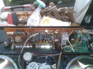
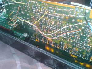
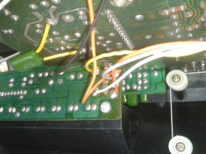
Hi, I can't even find a schematic for a Helix-4636 aka WATSON RR 5600 so that would be a start! Where would you wire your new RCA input socket to?

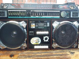
I am sick of this lovely looking box just sitting on a shelf in my garage looking all pretty but never getting used and I know I could use a FM trasmitter or cassette adapter but if someone would be kind enough to take the time to answer this, I would be very very grateful and get right on it immediately :yes:


helix.jpg
 

Smeats

Member (SA)
Feb 14, 2015
82
3
8
48
Perth, Scotland, UK
JVC Floyd said:
if it has external mic inputs you can wire the rca cables straight to the board after removing the mic sockets.
Just looked inside and it has a built in mic! Is it Just a matter of unsoldering the 2 wires from that (leaving the other ends attached to the PCB) then solder them to the new RCA sockets and running a wire from the new sockets to ground?
 

Smeats

Member (SA)
Feb 14, 2015
82
3
8
48
Perth, Scotland, UK
Cpl-Chronic said:
En MIc inputs are much more sensitive than a proper LINE IN circuit. It wouldn't work very well & your imput would be saturated.
thanks cpl! had a feeling it wasn't going to be that simple,
I wanted to find where the radio input +ve and -ve goes as it should be at the correct signal leval for an mp3 player but without any diagrams it's not obvious!
 

JVC Floyd

Inactive (Delete)
May 6, 2009
7,322
419
83
54
Maryland USA.
you need a dedicated mic input jack for my idea to work, i did this one my trident cx43f and it works great but it has external mic input jacks.
 

Smeats

Member (SA)
Feb 14, 2015
82
3
8
48
Perth, Scotland, UK
Superduper said:
Lets put it this way, mic inputs run about 2mv while Line inputs range from 150mv to 1.5v(1,500mv).
Just read your pinned thread on line in Super Duper! Tape, radio and mic can all have different signal levals and can all have their own pre amp circuit!! Sounds like a total mine field for damage if you don't know what you are doing. I am now unsure how or if to proceed with this little project! :'-(
 

Superduper

Member (SA)
If you are able to do some sherlock holmes with a digital meter, you will find that the function switch is the best place to tap into. That's because all the signal levels are pretty much equalized at that point so line-levels are an appropriate signal to inject at that location. The function selector is a multi-pole switch that switches the various functions (tape, aux, phono, radio) and pipes it to the preamp for processing. You won't want to tap into the radio circuit since that will interfere/confilct with radio audio. However, it is possible to pipe it into the phono function since presumably, you don't have a phono hooked up and at that point, the signals would have already been boosted to the proper signal level. However, if you don't have a phono function and only have tape/radio, then that's more problematic since tape function usually requires the deck to function to turn on the amp.

However.......... somewhere in the archives, I did do a line-in add mod for a Wards 3996 Airline, and that basically took the radio signals and put them through a switched 1/8" phono jack. Normally radio would work fine with nothing connected to the jack. When a 1/8" plug in inserted into the jack, it switches out the radio signals and instead, takes the signal from the aux jack. Perhaps that's the easiest way to do it for you.
 

Cpl-Chronic

Member (SA)
May 14, 2012
2,029
31
48
Windsor, Ontario, CANADA
Conceptually, I would try to tap into some location on the pre-amp stage, somewhere forward of the tone controls so that you can still adjust volume, bass, treble, etc. & then amplified by the main AMP IC's or transistors.......

Tap into that location with your RCA wires & use the right type of switch, maybe a 3 pole switch, to turn that home-made splice on & off....

Basically the signal input at the preamp stage would have 3 conductors, Gnd(-), L(+), R(+) just like a mini-stereo plug has a common(-), L(+), R(+) connection.

Super can correct me if I have that wrong but from my limited knowledge, I think that's how it breaks down as far as raw connections. You just have to find out where those points are on the preamp board/stage & tap in....right?
 

goodman

Member (SA)
Jun 14, 2011
2,330
236
63
50
Bulgaria
Smeats, please make a some good pictures of inside the boombox.
To see boards and to give you advice. :yes:
 

Smeats

Member (SA)
Feb 14, 2015
82
3
8
48
Perth, Scotland, UK
Superduper said:
If you are able to do some sherlock holmes with a digital meter, you will find that the function switch is the best place to tap into. That's because all the signal levels are pretty much equalized at that point so line-levels are an appropriate signal to inject at that location. The function selector is a multi-pole switch that switches the various functions (tape, aux, phono, radio) and pipes it to the preamp for processing. You won't want to tap into the radio circuit since that will interfere/confilct with radio audio. However, it is possible to pipe it into the phono function since presumably, you don't have a phono hooked up and at that point, the signals would have already been boosted to the proper signal level. However, if you don't have a phono function and only have tape/radio, then that's more problematic since tape function usually requires the deck to function to turn on the amp.

However.......... somewhere in the archives, I did do a line-in add mod for a Wards 3996 Airline, and that basically took the radio signals and put them through a switched 1/8" phono jack. Normally radio would work fine with nothing connected to the jack. When a 1/8" plug in inserted into the jack, it switches out the radio signals and instead, takes the signal from the aux jack. Perhaps that's the easiest way to do it for you.
Hi Superduper, found the thread with your mod and it looks like it would be the best solution, where can I find a switched phono jack, tried searching but no luck so far :hmmm:
 

Smeats

Member (SA)
Feb 14, 2015
82
3
8
48
Perth, Scotland, UK
goodman said:
Smeats, please make a some good pictures of inside the boombox.
To see boards and to give you advice. :yes:
Here is a pic of the main PCB, all the radio circuitry is on the right, tape in the centre and amp on the right

2015-03-01 13.57.29.jpg

on the opposite side there are 3 wire going from the radio part of the pcb to another pcb for the 5 band balance equalizer controls, left and right channels (orange an white) and the grey is ground I think!

2015-03-01 13.59.57.jpg


Here is the wires connected at the equalizer pcb closer up


2015-03-01 14.00.46.jpg


I think this is where I should put my line in to but please correct me if I'm wrong! :-)
 

goodman

Member (SA)
Jun 14, 2011
2,330
236
63
50
Bulgaria
Smeats, thanks for pictures.
On last 2 pictures you show connection from main board to LED METER.
This isn't place to connect anything!!!


This Is my vision about boards:
Radio and main is on one big board. Not easy to find radio out ...
Is it possible to connect line in on tape head in jack, but sound will be distorted....
Wait for advice from other members, before do anything wrong...
 

Reli

Member (SA)
Dec 24, 2010
6,320
452
83
USA
Wow, all that stuff mounted to one HORIZONTAL board. I hope there's some kind of ledge that helps support it on the rear case.
 
Status
Not open for further replies.