Sharp WF-939 channel dead - Help!

Status
Not open for further replies.

wills15

Member (SA)
Jan 29, 2012
142
0
16
Australia
Hey Guys,

I have this beater of a Sharp WF-940 (939 with Dolby). It's a personal 'grail' of mine, so I really want to get it working, and they're selling for big $ on eBay, so can't get another cheaply.

When I got it, it had sustained water damage, had a dead channel, no FM, no tape.

Inside was dry-joint central. I've touched up a lot of solder joints and replaced suspect capacitors. FM is now working, one channel is STILL NOT WORKING!!!

So frustrated, I've tried swapping amp ICs, equaliser ICs, equaliser transistors to no avail.

Power amp is definitely working, I can hear hiss from the dud channel, and if I turn the volume up full on the dead channel, I can softly hear the bass of the music... but perhaps this is just crosstalk in the main amplifier?

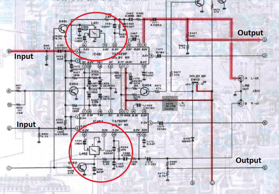
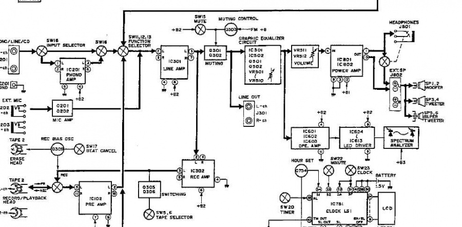
Here is a block diagram...


Preamp must be working, as when I connect a device to the line-out, both channels are working. Spectrum also only shows a reading for an input from the working channel.

Apart from dry solder joints, is there anything I could've missed?
 

wills15

Member (SA)
Jan 29, 2012
142
0
16
Australia
Also, if anyone has a good quality copy of the service manual for this model, I'd be very interested, mine has lots of sections missing.
 

docs

Member (SA)
Jun 26, 2010
2,558
381
83
52
United Kingdom
You definately need the schematic.
What about the volume pot ?
The idea really is to try and trace the route the audio takes, since somewhere between the amp and the speaker there is a fault, assuming the amp is good as you say.
What did you do to check the amp IC was good ? You can try and jumper the pins from the good channel to the bad channel to see if audio is present. You could also connect a speaker to the bad channel pin and see if you get anything.
Do you have an audio injector ? This gives you a great way of simulating sound at each component and move along until you find the part the sound stops.
 

wills15

Member (SA)
Jan 29, 2012
142
0
16
Australia
Thanks for the reply. I swapped the Amp ICs, and the same channel (left) was dead - if the ICs were at fault, the right channel would've been dead after I swapped them.

The fault is before the volume sliders, as the spectrum analyser is before the volume control in the circuit, and it shows no reading when input is played through the left channel.

Yeah, I really do need the schematic... hopefully someone of here has it.

Don't have an injector, but will look into it if I find the schematic.
 

BoomboxLover48

Member (SA)
Dec 3, 2010
5,747
262
83
Chicago, IL
Try to look for zener diodes on both channels and compare the readings to see if they match. Signal tracing would be the best option once you get the schematics.
 

wills15

Member (SA)
Jan 29, 2012
142
0
16
Australia
Ok guys, I found the problem by tracing the signal as decribed above...

An one of the dolby LC filters (variable inductor?) has gone open circuit. When I short it out, the channel comes back on.

Now, I have no idea how to measure the good inductor, in order to find a replacement, nor do I know how to tune it properly once I do find one.

Anyone know anything about these components? I thought of just substituting one from a junk piece of equipment, or just shorting it out and running it like that.

Markings are:

'LL00'
'84MF'
'Ja'

Any help appreciated.
 

Superduper

Member (SA)
wills15 said:
Ok guys, I found the problem by tracing the signal as decribed above...

An one of the dolby LC filters (variable inductor?) has gone open circuit. When I short it out, the channel comes back on.

Now, I have no idea how to measure the good inductor, in order to find a replacement, nor do I know how to tune it properly once I do find one.

Anyone know anything about these components? I thought of just substituting one from a junk piece of equipment, or just shorting it out and running it like that.

Markings are:

'LL00'
'84MF'
'Ja'

Any help appreciated.
They are called LCR meters. Sencore makes some decent ones.
 

wills15

Member (SA)
Jan 29, 2012
142
0
16
Australia
Sencore is probably a bit out of my price range, but I'll look into getting a cheaper one.

I'm not going to be using Dolby at all, so what do you think about just shorting the inductor out? It seems to work fine when I do this... I just don't want to damage anything else.
 

Superduper

Member (SA)
As you've already noticed, everything passes through the Dolby chips. Even if you don't use it, it does make a difference in the circuit. Audiophiles would consider shorting it blasphemy. But to be completely honest, most boombox guys don't have a good enough ear and are perfectly happy with "raw" unrefined sound. Without studying the circuitry, I can't comment on shorting it or not. It's definitely there for a reason and the purpose can't be known by speculating. If you do short it, are you going to short the other side too to balance it? That inductor and the associated circuitry is probably calibrated so taking it out of the equation changes the calibration and circuitry and behaviour.

Are you sure you read the markings right and are you sure it's an inductor? Inductor values are usually in microhenries (uH).
 

wills15

Member (SA)
Jan 29, 2012
142
0
16
Australia
Yeah, I'm not too concerned about the sound. But I've just opened up the the inductor and found the break, so I might try resoldering it first.

Not sure if it's any use. but here is the circuit...


Thanks for your help!
 

Superduper

Member (SA)
That is a resonant circuit, probably a filter. Certainly looks important enough since the effect is calibated for that circuit design. If possible, I would definitely recommend doing the microsurgery to restore, as much as possible, the inductor coil.

Here is some information regarding what RLC circuits can do:

A circuit containing L,C and R at a certain frequency can make L and C (or at least their electrical effects) completely disappear! The LCR circuit can appear to be just a capacitor, just an inductor, or solely a resistor! Not only that, the series LCR circuit can magnify voltage, so the voltages across individual components within the circuit, can actually be much larger than the external voltage supplying the circuit. LCR circuits can also dramatically change their impedance to offer more or less opposition to current at different frequencies. All these effects can be used separately or together to make the wide range of electronic devices that use AC.
The issue with just shorting it is that the rest of the filter components remain so the entirety of the circuit and it's design purpose has changed including the effects to the circuit.
 

wills15

Member (SA)
Jan 29, 2012
142
0
16
Australia
Great, thanks again. Microsurgery won't be too hard, if it breaks again after this I'll probably short both channels and see how it sounds.
 
Status
Not open for further replies.