I have a mini Sharp where it comes in stereo but the LED lights up very dim. I changed LED and resistor but still only getting less than a volt at LED  any ideas I have no scheme
any ideas I have no scheme any ideas I have no scheme The original LED was same. Little under 2vchar said:YOU must use 1 volt smd led


Theres just not enough voltage so I need to find out why 
WRONG!char said:YOU must use 1 volt smd led
Norm this is the QT27. I see what your saying about positive voltage at both cathode and anode.Superduper said:WRONG!char said:YOU must use 1 volt smd led
Bill, the stereo indicator lamp circuit is NOT as simple as you would think. This circuit normally operates by sinking the LED to ground through a control device. The cathode of the LED, if an led is used, usually grounds through either an MPX decoder chip (95%) or transistor. The Anode side of the led is usually fed a positive voltage. The cathode side, however might also see positive voltage, but less so. The difference, determines whether the led is sufficiently forward biased to light. The voltage at the cathode side will vary depending upon the MPX controller. Obviously, depending upon the appurtenant circuitry, and the algorithm for which the MPX decoder is designed, the threshold for when it lights and how brightly it lights will vary. In fact, the dropping resistor for that sinking circuitry probably isn't even the one you changed. Although this is how the stereo LED circuitry usually works, it varys depending upon the boombox, the mpx decoder chip used, etc. This simply isn't a situation where one can tell you change this and it's fixed. The voltage at the led anode can range from 3-9 volts. Who knows what it's supposed to be for your boombox? Also, what's the cathode voltage supposed to be? Yep, that's right, you probably will see positive voltage at both legs of the led. All I can suggest is that you acquire a manual and do voltage checks. What boombox is this anyhow?
Exactly right. And the difference in voltage between the two legs will determine if there is enough forward bias to light the LED to proper brightness. Unlike a simple 2v+ on cathode and anode to ground, this is something that is not as easy to grasp. So when you say you are seeing less than 1 volt at the led, once again..... I don't know what that means. Are you measuring at the cathode? Anode? What's the voltage at the other leg... see what I'm saying? Conventional lighting circuits suggests that anode positive, cathode ground. But this isn't a lighting circuit. It's a dynamic indicator circuit and it's behaviour is dictated by the circuitry around it and what is happening in that circuit.baddboybill said:Norm this is the QT27. I see what your saying about positive voltage at both cathode and anode.
Yes I'm getting. .64 at cathode and 2.34v at anode so that must be to much positive voltage at cathode to not allowing it to light brighterSuperduper said:Exactly right. And the difference in voltage between the two legs will determine if there is enough forward bias to light the LED to proper brightness. Unlike a simple 2v+ on cathode and anode to ground, this is something that is not as easy to grasp. So when you say you are seeing less than 1 volt at the led, once again..... I don't know what that means. Are you measuring at the cathode? Anode? What's the voltage at the other leg... see what I'm saying? Conventional lighting circuits suggests that anode positive, cathode ground. But this isn't a lighting circuit. It's a dynamic indicator circuit and it's behaviour is dictated by the circuitry around it and what is happening in that circuit.baddboybill said:Norm this is the QT27. I see what your saying about positive voltage at both cathode and anode.
I understand. Thanks NormNot necessarily. Do we know for sure that anode voltage is correct?baddboybill said:Yes I'm getting. .64 at cathode and 2.34v at anode so that must be to much positive voltage at cathode to not allowing it to light brighter
Unfortunatly without scheme noSuperduper said:Not necessarily. Do we know for sure that anode voltage is correct?baddboybill said:Yes I'm getting. .64 at cathode and 2.34v at anode so that must be to much positive voltage at cathode to not allowing it to light brighter

")
Thank you I’m gonna replace led and check pathcaution said:Never seen a Wards service manual, you might have to trace the circuit out a bit. How are your drawing skills?
It shouldn't be much, the stereo separation function and stereo LED output are usually just pins on the MPX IC with a few passives in between.
I will try that thank youcaution said:Good deal, if that doesn't work take closeups of both sides in the tuner area, maybe we can figure out how many parts are at play
Norm I have not measured because I have to try and hook up so it will work but I can actually hear the difference when in stereo mode.Superduper said:Montgomery wards actually do publish service manuals. I have a few including the GEN 3998a, but no 3995a or the popular 3996. As for the LED, did you do any testing? Did you test for voltage at both cathode and anode side to confirm that there is at least 1.6v or more difference measured from either side to ground? Also are you sure that it is actually locking onto stereo mode? In other words, is there a noticeable difference in sound quality between stereo and mono modes? Usually the difference is unmistakable.

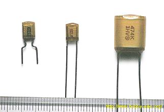
Thank you but I can’t seem to locate any. I have a 1000uf electrolytic but they have +- leads where the polystyrene do not. Not sure what to docaution said:It shorted, good job finding the bad part!
Use the same type if you have the option. They are more expensive than ceramics and so they probably spent a little extra on it for good reason, either in a tuned circuit or to improve the quality of the audio signal. Ceramics, polystyrenes, polypropylenes, tantalums, polyester... they all have different characteristics at different frequencies. Some start possessing more inductance than others at higher frequencies, blah blah...