Wm 10 type walkmans are slightly difficult to mend because of their tiny size.
You can download the service manual attached at the end of this post to give you a clear idea of technical details
Here are some pointers/tips
1)OPENING UP: a)unscrew the 2 central hinge screws to remove the cassette door
b)unscrew the 4 chasis screws on the four corners of the back
c)unscrew the ornamental dial of the volume control (using tweezers in the 2 holes or a pair of pointed scissors)
d)remove the battery cover and battery
2)'NON WORKING'???: If the unit doesn't power up there are 3 common things to look into before ripping things open & worsening things:
a) plug in a pair of earphones to complete the 'power on' circuit/power saving feature
b)If an old belt is jammed it prevents switching on/powering on...replace the belt
c)simple corrosion: Corrosion is mainly seen towards the -ve terminal..scrape off with a sharp blade/emery paper or use commercial dissolving solutions
d)BAAAAAD corrosion") ): The whole battery compartment and surrounding areas look swamped with the ooze...clean up and carefully unscrew the circuit board to check underneath....the wire from the -ve battery terminal to the pcb gets disconnected by the corrosion eating into the point of soldering.
): The whole battery compartment and surrounding areas look swamped with the ooze...clean up and carefully unscrew the circuit board to check underneath....the wire from the -ve battery terminal to the pcb gets disconnected by the corrosion eating into the point of soldering.
3)SCRAPING/Scratching/Freewheeling NOISES: Sony provides felt spacer strips stuck onto the inner surface of the metal shell of the walkman and also on the surface of the pcb to maintain a certain distance to prevent scraping of moving parts with the shell. These spacers get powdery with age & can be replaced quite easily
4)Headphone sound problems. The supply to the headphone socket is via a flexible pcb which sometimes goes kaput in one of its lines.Either link a thin wire from start point to end point or if the break in connectivity is located bypass it by carefully scraping the protective varnish on either side and soldering a small wire segment
OPENING UP
FIRST REMOVE THE BATTERY COVER & BATTERY:
carefully slide off the plastic battery cover in wm30 types and carefully use the plastic (breakable) spring based push switch on the inner surface of wm 10/20 types to avoid ruining the battery cover


Now remove the central 2 hinge screws to enable removal of the cassette door.
After screw removal gently slide out the cassette door till it comes off...I've left the sliding portion 'pulled out' so that you'll have a clearer idea


Now we remove the ornamental volume control dial with its central 'screw'. A pair of fine tipped scissors or the tips of tweezers will do the job.
Roll down the volume to ZERO , engage the tips of the tweezers into the two tiny holes and turn firmly counterclockwise, rotate till the screw, the volume dial and the transparent washer come off.
we now unscrew the remaining four screws on the back holding the shell in place

Now lift up the mechanism and ease it back, up and out

Note the battery pull out strip of plastic...care should be taken to ensure it is free when re assembling

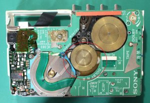
the internal mechanism removed from the shell...

careful not to loose the switch sliders...the right orientation is with the springy split side facing down.

when reassembling:
1)make sure the switch positions are Dolby -on , Tape-metal and orient the sliders accordingly.
2)Make sure you pull free the battery releasing plastic strip
3) If the blue/green plastic inserts that decorate the sockets of the play/stop come loose...stick them back with suprglue...same for the adapter socket white plastic insert.
4) Insert the mechanism at an angle first to engage the play/stop/ff/rew switches and then flatten it down while pushing in keeping an eye on the a)battery release & b)switch sliders.
The casette door is fixed back by carefully guiding the leg like slender projections into their grooves on either side(easy if you have the hinge 'OPEN' with one hand on the inside). Finally the central slider is aligned with the shell holes and the screws screwed back in. Sony recommends placing in a cassette while actually tightening the back four screws for 'support'??. I usually like to stick 1mm felt sticker patches on the pcb before reassembling to replace the origianl felt pads that are very rarely intact...to prevent rubbing of moving parts with the shell and resultant noises
CIRCUIT BOARD HANDLING PRECAUTIONS:
1)ENDING UP WITH MORE LOST CONNECTIONS : Sony makes use of
1)ultra flexible and ULTRA FLIMSY flexible connectors that can tear &
2) the battery connections/tuner dial connections in wmF10 types are of a very thin (26? gauge) wire that very easily snaps off the soldered joint
CAT 5 cable/ telephone wire might be a source for such wire
2)CHIP DE-SOLDERING/DE MOUNTIUNG
If you overzealously move around/twist a pcb of the thickness used in a wm10...you might be able to even crack some of the copper lines...but worse than that during the flexing...the mounted resistance /capicitor chips may loose their solder joint and develop a loose contact that is maddening to find/trouble shoot and even more maddening to resolder...so watch out!!
SCRATCHING NOISES:
While moving parts scraping against the inner surface of the walkman shell is the most common cause and is easily remediable using felt spacers on the pcb....there is a rare situation of motor assembly problem related noise.
If a walkman produces a motor hum but there is no movement during play the most common assumption before opening up is...belt replacement. BUT sometimes you get hit by a jamming of the motor parts .The simplest method of setting things right is to coax the assembly back into movement by manually turning the tape transport wheel(supply reel/take up reel). If this doesn't help you'll have to open up the motor assembly.
Once the shield plate over the motor is removed the spinning disc with holes in it (Hysteresis plate) is visible normally spinning above the flat plastic plate with coils (the stator coil). Below this is the actual rotating component with a permanent magnet in a disc form. This sometimes ends up rubbing against the motor sleeve assembly below all the more because it unfortuantely is some sort of magnetic stainless steel that loves to have the magnet stuck to it If sony had used some hard plastic/aluminium this wouldn't have occurred.
This arises due to a problem with the spacer which actually is visible in a closed walkman from its outer surface as the spindle onto which the gear wheel sits with a locking washer. If this gets displaced outwards even a fraction of a mm it allows the motor magnet to get stuck/scrape and readjusting this is a solid half hour job
One thing that seemed to help maintain the space was inserting a thin washer made by cutting a plasticized visiting card using a coin as a cutting templete and then punching acentral hole using a standard paper punch. I inserted this between the coil and the hysteresis plate
Looks like sony has had a lot of negative feedback with reagrds to this assembly. So you might get to see two types of assemblies
TYPE 1 (Sony part 3133 205 A): The flat magnetic rotor has a short round ended axle that ends up on the inside of the tape transport wheel underneath the area that has the lock washer to keep the transport wheel in place.The lock washer assembly is a separate part and has a small plastic washer underneath to maintain the space we have been talking about.
TYPE II (Sony part 3133 182 A): The axle of the rotor goes right through the transport wheel terminating in an end with a groove to take the lock washer,the axle has a built on mini ball bearing & there is a small flat spacing washer that keeps the coil away from the rotor...


Note the frictional scratch marks on the Type I on the right
DUPLICATING the flexible pcb connector from the radio to main board (I know, this one is crazy!):
use a wire cutter or struggle as I did with a pair of blunt scissors to remove the plastic insulation off 6 inch lengths of multistranded insulated wire. Twist the strands to form a flexible multistrand wire without insulation.
Apply rubber adhesive onto a tracing acetate sheet on the matt surface side after tracing the outline of the connector. Now stick wires along the 'copper track' lines. After finishing stick another acetate sheet on top to sandwich the wires between.


sometimes you have a flex connector in which only one or two lines are cut. In such situations you may consider reinforcing the crack/cut line area with superglue followed by cellotape. The connections can nbe re-established by running 4 filaments of wire twisted together from the start to stopsolder points on TOP of the existing flex connector and these can be stuck in place with cellotape which alos helps reinforce the whole connector.
BATTERY TERMINALS CORRODED?MISSING?BROKEN
Usually the battery terminal that comes into contact with the raised end (+) of the battery, never gets into trouble....but YESSIR!!! I have had 'semi junkers' with that piece of contact sheet metal missing. I tried a nice shiny bit of razor blade metal trimmed with scissors...fit wonderfully......BUT...wouldn't accept solder!!
So remember replacing the terminal with a carefully shaped piece of copper sheet (silver plated /Ni or Cr plated/Plain) solves the problem because there's the solder joint to consider.
The terminal coming in contact with the + end is just a squarish flat sheet but the - terminal is a square plate with a central triangle cut and pushed forward forming a spring ...OUCH
1) If you just want the walkman to work you could either solder a L bent copper terminal onto the plate or the top portion of any regular contact terminal spring salvaged from a battery holder(the whole spring will be too big...so use just the top portion)
2) If you are actually tring to 'restore' then it helps to have another normal walkman open and then to try and duplicate the shape of the -ve terminal...I'll try posting some pics of a normal terminal soon...
battery compartment LID REPAIR:
sometimes you'll be lucky to get a wm 10 type walkman with the battery lid loose but otherwise intact. The battery lid breaks up into 3 parts the extrenal housing, the internal plastic that holds thebattery in place and a small plastic sliding spring that actually locks into place securing the lid.
When someone is careless or unaware as to how to open a lid they end up breaking off the end portion. NOTE: The plastic is extremely durable so if you still have the ned piece/tip stick it with superglue ...it'll go on for many more years...IF NOT......the DocP way
make a keyhole in the broken end with a small hobby drill (...your dentist or http://www.dremel.com) now repair the misiing portion with an add on of auto curing acrylic. Shape it up after hardening to the correct length with a slight sloping thickening at the end to lock...see pic. helps once in a while to have an intact (non mint) walkman ready for dismantling to compare components/parts/connections when you are 'non technical' like me


WON"T PLAY AT ALL:.... after replacing belt...autostop too sensitive...:?
Normally the auto stop is supposed to 1) make the play mode stop at the end of a tape or 2)prevent these tiny fellows from eating tape.
Sony's troubleshooting guide mentions replacing the function plate assembly (with all the play/fw/rew switches) if depressing the pinch roller into its socket triggers autostop when the battery is out (no power) That wasn't my problem, but I tried a transplant...no difference.
The second option is the replacement of the 'shut off lever return spring' .This is a very thin spring that sometimes just slips off track....but access to it means really dismantling your walkman down to the basic level...watch out...
SOUND/AUDIO problems: I wouldn't normally expect the pre amp IC to die out ...so audio problems might be traceable :
At socket level
1. Does the headphone socket look like it has a little wobble/play - this is quite common with some of these units - the plastic edge that holds it firm to its support bracket breaks and each wobble that occurs thereafter has the hazard of messing the audio connections coming towards the socket
At Board level
1. There are these leaf switches that are activated for FW/REW/Play ..when you unscrew the board for repairs and screw it back it if these aren't aligned right and a second set of leaves are in contact the motor will run but you'll not get sound.
2.undersurface shorting. There are solder points on the undersurface of the PCB that might come into contact with metallic parts if the 'felt' patches have deteriorated or haven't been replaced. I have managed on occasion by giving a thin coat of varnish or nailpolish over all exposed solder.
3.undersurface mounted chips dislodged : I've had a situation where a mounted resistance popped off and I just couldn't put if back on with the huge soldering Iron I had back then...so I just dropped a drop of solder beween the end contacts and surprisingly it worked fine
If the fallen off/defective component happens to be a capacitor I guess a replacement is the only way and instead of having a complete sound loss one might(?) expect a bit of waxing/waning/slow fade off of sound due to improper capacitor functioning ???
Volume pot.
Very rarely if the spacer is left out shorting contacts occur at the volume pot. shorting out sound
Flexible Cicuit board connector:
There's one that leads to the headphone socket and in the days that I had patience (instead of patients ) & time I've had to mend a few broken tracks by jumping them with extra thin gauge wire(salvage some from a phone cord)
Playback head dead?
Most of the troubleshooting tips outlined are for folks like me who probably have a multimeter and aren't that good at actually using one
Duplicating cassette door windows - w800 ( Not exactly Fatdog work quality...but take courage from this humble attempt") )
)

Requirements :
1.a plastic/clear acrylic sheet salvaged from a CD cover
2) a scalpel Bard Parker knife with a no. 11 blade or a hobby knife like xacto with a no.11 blade
3)SUN CONTROL film in black and silver
4)color adhesive sticker....I hit an automotive repairs/decors shop


....omputer cut letters in reverse stuck from behind, black acrylic paint....Not exactly screen printing, but not bad
Duplicating the w800 Pause Slider:
These double cassette walkmans come with a slider for the pause function that engages the actual switch below at 90 degrees instead of head on. I think the origibnal design has a U shaped plastic loop that engages the switch. All that mine had was one leg. So I decided I'd atleast give it another leg while duplicating.
MOULD : I used a tiny inch square box to make my split mould using addition silicone. I got the main slider knob details on one half and a tiny tube like impression corresponding to 'one leg' on the other half. Just near this was a tiny 'dent' like impression corresponding to the spot where the original 2nd leg was. So I drilled a small hole in this location to approximately the same depth as the first leg using a 'tapering fissure diamond' ....that's one of the things we dentists use on your teeth folks...poor Doc P doesn't have any fancy drills ...only his dental tools
All mass produced plastic components are made in molds & tapped out - so the first thing is to figure out how to align the component such that you can make a top half mould and a bottom half mould without allowing any locking up of the component due to undercuts created by improper alignment.
Sometimes there are non functional slots or grooves which can be 'blocked out' with candle wax.
In dentistry small moulds are made (to make acrylic crowns) in a small inexpensive brass conatiner called a Jacket Crown Flask. It is more like a small cylindrical box that opens halfway .slots on one half and brass extensions on the other enable precise closing of the halves.
Plaster of paris or dental stone makes an excellent one time use mould because it is accurate & rigid - but due to the rigidity it is sometimes cumbersome to pull the component out while making the mould.
An alternative is to first embed the component in wax or plasticine with the top half exposed. Mix putty silicone and press it over the component. Remove. Now inject low viscosity light bodied silicone into critical areas like the teeth and place the putty impression over the component again. Remove. You now have the upper half of the mould in Putty with important details in light body. Remove the component from the plasticine/wax & seat the top half into the mould half made. Smear alittle vaseline over the exposed areas of silicone & repeat the above procedure to make the second mould half.
The two mould halves are now used in conjunction with any chemically curing plastic to form the component
Duplication Material:
I use acrylic material available in clear/dental pink and dental yellow-white coz...that's the stuff i have The second photo shows the rough product with the excess overflow 'called flash' which is trimmed to produce what you see in photo 3.
A dental lab will convert the acrylic to metal by investing and casting...


As mentioned earlier this is both REPAIR and DUPLICATION. Notice only one leg in the original slider and notice the second leg in the duplicate made possible by drilling a hole (to form the negative impression) corresponding to the size/location of the missing leg
Adding a leg to the original slider is possible ...but a joint is always a weak spot. This way the duplicate becomes a single piece durable replica with repairs added in
In situations where you only have a picture of how your slider should look...make a prototype by grinding away/cutting away a rectangular pencil eraser to the required shape for duplication or use a combination of candle wax carved to shape with grooves and such and a strip of old CD case acrylic (for support) to make the actual sliding portion ........
Battery Compartment Problems:
1. Battery corrosion Gunk ....can be cleaned up
2. Broken battery terminal 'spring' contact : gently dislodge the remaining metal from the plastic backing to 'create' a new spring contact...works fine
3. Compartment plastic chipped /broken...this gets bad ...coz the battery cover won't stay down...can be fixed by a bit of patching up as below :
a) remove the chipped/damaged portion completely (I use dental tools...Dremel has agood assortment of 'hobby drill' tools quite similar...www.dremel.com)


next we salvage some thin white plastic from a CD case
and then trim it down to size/shape and thickness as shown...

Then stick it up in place with a drop of Cyanoacrylate (Superglue) ...this example is a typical 7-10 minutes shoddy repair job of me searching for solutions ...if you really want to perfection is just 15 min away

NOTE: I haven't bothered a)cleaning up the glue job the previous owner attempted and b)extending the plastic all the way down on either side of the battery terminal to be able to show a fast easy fix...
It isn't that difficult making a battery cover from scratch too ....just that it won't be a Sony original ...but will work
Parts shared between wm10 series & wm F65 (some parts with wmF15 too)
1. x-3315-308-0 (wheel assy, reverse)
2. 3-315-405-00 (belt)
3. A-3133-205-A (Wheel Assy block assy, motor)
4. x-3315-315-0 (gear assy, take up reel)
5. x-3317-508-1 (flywheel assy)
6. X-3133-002-A (wheel block assy, reverse)
7. A-3133-206-A (Riveting assy, motor sleeve)
http://www.stereo2go.com/displayForumTo ... 4111974324
You can download the service manual attached at the end of this post to give you a clear idea of technical details
Here are some pointers/tips
1)OPENING UP: a)unscrew the 2 central hinge screws to remove the cassette door
b)unscrew the 4 chasis screws on the four corners of the back
c)unscrew the ornamental dial of the volume control (using tweezers in the 2 holes or a pair of pointed scissors)
d)remove the battery cover and battery
2)'NON WORKING'???: If the unit doesn't power up there are 3 common things to look into before ripping things open & worsening things:
a) plug in a pair of earphones to complete the 'power on' circuit/power saving feature
b)If an old belt is jammed it prevents switching on/powering on...replace the belt
c)simple corrosion: Corrosion is mainly seen towards the -ve terminal..scrape off with a sharp blade/emery paper or use commercial dissolving solutions
d)BAAAAAD corrosion
): The whole battery compartment and surrounding areas look swamped with the ooze...clean up and carefully unscrew the circuit board to check underneath....the wire from the -ve battery terminal to the pcb gets disconnected by the corrosion eating into the point of soldering.3)SCRAPING/Scratching/Freewheeling NOISES: Sony provides felt spacer strips stuck onto the inner surface of the metal shell of the walkman and also on the surface of the pcb to maintain a certain distance to prevent scraping of moving parts with the shell. These spacers get powdery with age & can be replaced quite easily
4)Headphone sound problems. The supply to the headphone socket is via a flexible pcb which sometimes goes kaput in one of its lines.Either link a thin wire from start point to end point or if the break in connectivity is located bypass it by carefully scraping the protective varnish on either side and soldering a small wire segment
OPENING UP
FIRST REMOVE THE BATTERY COVER & BATTERY:
carefully slide off the plastic battery cover in wm30 types and carefully use the plastic (breakable) spring based push switch on the inner surface of wm 10/20 types to avoid ruining the battery cover
Now remove the central 2 hinge screws to enable removal of the cassette door.
After screw removal gently slide out the cassette door till it comes off...I've left the sliding portion 'pulled out' so that you'll have a clearer idea
Now we remove the ornamental volume control dial with its central 'screw'. A pair of fine tipped scissors or the tips of tweezers will do the job.
Roll down the volume to ZERO , engage the tips of the tweezers into the two tiny holes and turn firmly counterclockwise, rotate till the screw, the volume dial and the transparent washer come off.
we now unscrew the remaining four screws on the back holding the shell in place
Now lift up the mechanism and ease it back, up and out
Note the battery pull out strip of plastic...care should be taken to ensure it is free when re assembling
the internal mechanism removed from the shell...
careful not to loose the switch sliders...the right orientation is with the springy split side facing down.
when reassembling:
1)make sure the switch positions are Dolby -on , Tape-metal and orient the sliders accordingly.
2)Make sure you pull free the battery releasing plastic strip
3) If the blue/green plastic inserts that decorate the sockets of the play/stop come loose...stick them back with suprglue...same for the adapter socket white plastic insert.
4) Insert the mechanism at an angle first to engage the play/stop/ff/rew switches and then flatten it down while pushing in keeping an eye on the a)battery release & b)switch sliders.
The casette door is fixed back by carefully guiding the leg like slender projections into their grooves on either side(easy if you have the hinge 'OPEN' with one hand on the inside). Finally the central slider is aligned with the shell holes and the screws screwed back in. Sony recommends placing in a cassette while actually tightening the back four screws for 'support'??. I usually like to stick 1mm felt sticker patches on the pcb before reassembling to replace the origianl felt pads that are very rarely intact...to prevent rubbing of moving parts with the shell and resultant noises
CIRCUIT BOARD HANDLING PRECAUTIONS:
1)ENDING UP WITH MORE LOST CONNECTIONS : Sony makes use of
1)ultra flexible and ULTRA FLIMSY flexible connectors that can tear &
2) the battery connections/tuner dial connections in wmF10 types are of a very thin (26? gauge) wire that very easily snaps off the soldered joint
CAT 5 cable/ telephone wire might be a source for such wire
2)CHIP DE-SOLDERING/DE MOUNTIUNG
If you overzealously move around/twist a pcb of the thickness used in a wm10...you might be able to even crack some of the copper lines...but worse than that during the flexing...the mounted resistance /capicitor chips may loose their solder joint and develop a loose contact that is maddening to find/trouble shoot and even more maddening to resolder...so watch out!!
SCRATCHING NOISES:
While moving parts scraping against the inner surface of the walkman shell is the most common cause and is easily remediable using felt spacers on the pcb....there is a rare situation of motor assembly problem related noise.
If a walkman produces a motor hum but there is no movement during play the most common assumption before opening up is...belt replacement. BUT sometimes you get hit by a jamming of the motor parts .The simplest method of setting things right is to coax the assembly back into movement by manually turning the tape transport wheel(supply reel/take up reel). If this doesn't help you'll have to open up the motor assembly.
Once the shield plate over the motor is removed the spinning disc with holes in it (Hysteresis plate) is visible normally spinning above the flat plastic plate with coils (the stator coil). Below this is the actual rotating component with a permanent magnet in a disc form. This sometimes ends up rubbing against the motor sleeve assembly below all the more because it unfortuantely is some sort of magnetic stainless steel that loves to have the magnet stuck to it If sony had used some hard plastic/aluminium this wouldn't have occurred.
This arises due to a problem with the spacer which actually is visible in a closed walkman from its outer surface as the spindle onto which the gear wheel sits with a locking washer. If this gets displaced outwards even a fraction of a mm it allows the motor magnet to get stuck/scrape and readjusting this is a solid half hour job
One thing that seemed to help maintain the space was inserting a thin washer made by cutting a plasticized visiting card using a coin as a cutting templete and then punching acentral hole using a standard paper punch. I inserted this between the coil and the hysteresis plate
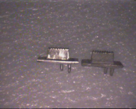
Looks like sony has had a lot of negative feedback with reagrds to this assembly. So you might get to see two types of assemblies
TYPE 1 (Sony part 3133 205 A): The flat magnetic rotor has a short round ended axle that ends up on the inside of the tape transport wheel underneath the area that has the lock washer to keep the transport wheel in place.The lock washer assembly is a separate part and has a small plastic washer underneath to maintain the space we have been talking about.
TYPE II (Sony part 3133 182 A): The axle of the rotor goes right through the transport wheel terminating in an end with a groove to take the lock washer,the axle has a built on mini ball bearing & there is a small flat spacing washer that keeps the coil away from the rotor...
Note the frictional scratch marks on the Type I on the right
DUPLICATING the flexible pcb connector from the radio to main board
(I know, this one is crazy!):use a wire cutter or struggle as I did with a pair of blunt scissors to remove the plastic insulation off 6 inch lengths of multistranded insulated wire. Twist the strands to form a flexible multistrand wire without insulation.
Apply rubber adhesive onto a tracing acetate sheet on the matt surface side after tracing the outline of the connector. Now stick wires along the 'copper track' lines. After finishing stick another acetate sheet on top to sandwich the wires between.
sometimes you have a flex connector in which only one or two lines are cut. In such situations you may consider reinforcing the crack/cut line area with superglue followed by cellotape. The connections can nbe re-established by running 4 filaments of wire twisted together from the start to stopsolder points on TOP of the existing flex connector and these can be stuck in place with cellotape which alos helps reinforce the whole connector.
BATTERY TERMINALS CORRODED?MISSING?BROKEN
Usually the battery terminal that comes into contact with the raised end (+) of the battery, never gets into trouble....but YESSIR!!! I have had 'semi junkers' with that piece of contact sheet metal missing. I tried a nice shiny bit of razor blade metal trimmed with scissors...fit wonderfully......BUT...wouldn't accept solder!!
So remember replacing the terminal with a carefully shaped piece of copper sheet (silver plated /Ni or Cr plated/Plain) solves the problem because there's the solder joint to consider.
The terminal coming in contact with the + end is just a squarish flat sheet but the - terminal is a square plate with a central triangle cut and pushed forward forming a spring ...OUCH
1) If you just want the walkman to work you could either solder a L bent copper terminal onto the plate or the top portion of any regular contact terminal spring salvaged from a battery holder(the whole spring will be too big...so use just the top portion)
2) If you are actually tring to 'restore' then it helps to have another normal walkman open and then to try and duplicate the shape of the -ve terminal...I'll try posting some pics of a normal terminal soon...
battery compartment LID REPAIR:
sometimes you'll be lucky to get a wm 10 type walkman with the battery lid loose but otherwise intact. The battery lid breaks up into 3 parts the extrenal housing, the internal plastic that holds thebattery in place and a small plastic sliding spring that actually locks into place securing the lid.
When someone is careless or unaware as to how to open a lid they end up breaking off the end portion. NOTE: The plastic is extremely durable so if you still have the ned piece/tip stick it with superglue ...it'll go on for many more years...IF NOT......the DocP way
make a keyhole in the broken end with a small hobby drill (...your dentist or http://www.dremel.com) now repair the misiing portion with an add on of auto curing acrylic. Shape it up after hardening to the correct length with a slight sloping thickening at the end to lock...see pic. helps once in a while to have an intact (non mint) walkman ready for dismantling to compare components/parts/connections when you are 'non technical' like me
WON"T PLAY AT ALL:.... after replacing belt...autostop too sensitive...:?
Normally the auto stop is supposed to 1) make the play mode stop at the end of a tape or 2)prevent these tiny fellows from eating tape.
Sony's troubleshooting guide mentions replacing the function plate assembly (with all the play/fw/rew switches) if depressing the pinch roller into its socket triggers autostop when the battery is out (no power) That wasn't my problem, but I tried a transplant...no difference.
The second option is the replacement of the 'shut off lever return spring' .This is a very thin spring that sometimes just slips off track....but access to it means really dismantling your walkman down to the basic level...watch out...
SOUND/AUDIO problems: I wouldn't normally expect the pre amp IC to die out ...so audio problems might be traceable :
At socket level
1. Does the headphone socket look like it has a little wobble/play - this is quite common with some of these units - the plastic edge that holds it firm to its support bracket breaks and each wobble that occurs thereafter has the hazard of messing the audio connections coming towards the socket
At Board level
1. There are these leaf switches that are activated for FW/REW/Play ..when you unscrew the board for repairs and screw it back it if these aren't aligned right and a second set of leaves are in contact the motor will run but you'll not get sound.
2.undersurface shorting. There are solder points on the undersurface of the PCB that might come into contact with metallic parts if the 'felt' patches have deteriorated or haven't been replaced. I have managed on occasion by giving a thin coat of varnish or nailpolish over all exposed solder.
3.undersurface mounted chips dislodged : I've had a situation where a mounted resistance popped off and I just couldn't put if back on with the huge soldering Iron I had back then...so I just dropped a drop of solder beween the end contacts and surprisingly it worked fine
If the fallen off/defective component happens to be a capacitor I guess a replacement is the only way and instead of having a complete sound loss one might(?) expect a bit of waxing/waning/slow fade off of sound due to improper capacitor functioning ???
Volume pot.
Very rarely if the spacer is left out shorting contacts occur at the volume pot. shorting out sound
Flexible Cicuit board connector:
There's one that leads to the headphone socket and in the days that I had patience (instead of patients ) & time I've had to mend a few broken tracks by jumping them with extra thin gauge wire(salvage some from a phone cord)
Playback head dead?
Most of the troubleshooting tips outlined are for folks like me who probably have a multimeter and aren't that good at actually using one
Duplicating cassette door windows - w800 ( Not exactly Fatdog work quality...but take courage from this humble attempt
)
Requirements :
1.a plastic/clear acrylic sheet salvaged from a CD cover
2) a scalpel Bard Parker knife with a no. 11 blade or a hobby knife like xacto with a no.11 blade
3)SUN CONTROL film in black and silver
4)color adhesive sticker....I hit an automotive repairs/decors shop
....omputer cut letters in reverse stuck from behind, black acrylic paint....Not exactly screen printing, but not bad
Duplicating the w800 Pause Slider:
These double cassette walkmans come with a slider for the pause function that engages the actual switch below at 90 degrees instead of head on. I think the origibnal design has a U shaped plastic loop that engages the switch. All that mine had was one leg. So I decided I'd atleast give it another leg while duplicating.
MOULD : I used a tiny inch square box to make my split mould using addition silicone. I got the main slider knob details on one half and a tiny tube like impression corresponding to 'one leg' on the other half. Just near this was a tiny 'dent' like impression corresponding to the spot where the original 2nd leg was. So I drilled a small hole in this location to approximately the same depth as the first leg using a 'tapering fissure diamond' ....that's one of the things we dentists use on your teeth folks...poor Doc P doesn't have any fancy drills ...only his dental tools
All mass produced plastic components are made in molds & tapped out - so the first thing is to figure out how to align the component such that you can make a top half mould and a bottom half mould without allowing any locking up of the component due to undercuts created by improper alignment.
Sometimes there are non functional slots or grooves which can be 'blocked out' with candle wax.
In dentistry small moulds are made (to make acrylic crowns) in a small inexpensive brass conatiner called a Jacket Crown Flask. It is more like a small cylindrical box that opens halfway .slots on one half and brass extensions on the other enable precise closing of the halves.
Plaster of paris or dental stone makes an excellent one time use mould because it is accurate & rigid - but due to the rigidity it is sometimes cumbersome to pull the component out while making the mould.
An alternative is to first embed the component in wax or plasticine with the top half exposed. Mix putty silicone and press it over the component. Remove. Now inject low viscosity light bodied silicone into critical areas like the teeth and place the putty impression over the component again. Remove. You now have the upper half of the mould in Putty with important details in light body. Remove the component from the plasticine/wax & seat the top half into the mould half made. Smear alittle vaseline over the exposed areas of silicone & repeat the above procedure to make the second mould half.
The two mould halves are now used in conjunction with any chemically curing plastic to form the component
Duplication Material:
I use acrylic material available in clear/dental pink and dental yellow-white coz...that's the stuff i have The second photo shows the rough product with the excess overflow 'called flash' which is trimmed to produce what you see in photo 3.
A dental lab will convert the acrylic to metal by investing and casting...
As mentioned earlier this is both REPAIR and DUPLICATION. Notice only one leg in the original slider and notice the second leg in the duplicate made possible by drilling a hole (to form the negative impression) corresponding to the size/location of the missing leg
Adding a leg to the original slider is possible ...but a joint is always a weak spot. This way the duplicate becomes a single piece durable replica with repairs added in
In situations where you only have a picture of how your slider should look...make a prototype by grinding away/cutting away a rectangular pencil eraser to the required shape for duplication or use a combination of candle wax carved to shape with grooves and such and a strip of old CD case acrylic (for support) to make the actual sliding portion ........
Battery Compartment Problems:
1. Battery corrosion Gunk ....can be cleaned up
2. Broken battery terminal 'spring' contact : gently dislodge the remaining metal from the plastic backing to 'create' a new spring contact...works fine
3. Compartment plastic chipped /broken...this gets bad ...coz the battery cover won't stay down...can be fixed by a bit of patching up as below :
a) remove the chipped/damaged portion completely (I use dental tools...Dremel has agood assortment of 'hobby drill' tools quite similar...www.dremel.com)
next we salvage some thin white plastic from a CD case
and then trim it down to size/shape and thickness as shown...
Then stick it up in place with a drop of Cyanoacrylate (Superglue) ...this example is a typical 7-10 minutes shoddy repair job of me searching for solutions ...if you really want to perfection is just 15 min away
NOTE: I haven't bothered a)cleaning up the glue job the previous owner attempted and b)extending the plastic all the way down on either side of the battery terminal to be able to show a fast easy fix...
It isn't that difficult making a battery cover from scratch too ....just that it won't be a Sony original ...but will work
Parts shared between wm10 series & wm F65 (some parts with wmF15 too)
1. x-3315-308-0 (wheel assy, reverse)
2. 3-315-405-00 (belt)
3. A-3133-205-A (Wheel Assy block assy, motor)
4. x-3315-315-0 (gear assy, take up reel)
5. x-3317-508-1 (flywheel assy)
6. X-3133-002-A (wheel block assy, reverse)
7. A-3133-206-A (Riveting assy, motor sleeve)
http://www.stereo2go.com/displayForumTo ... 4111974324
 Thanks for sharing, DocP. It's good to see you still around.
 glad you came over to Boomboxery with your knowledge of Walkmans and belts
 ") I'll have to do a bit of serious posting eh
I'll have to do a bit of serious posting eh